
Header height control system with multiple height sensors

a technology of header and height sensor, which is applied in the field of agricultural harvesters equipped with headers, can solve the problems of cutter sensor to leave, fully compress, and inability to reliably determine the height and/or and achieve the effect of accurate control of the height and tilt angle of the header

Active Publication Date: 2018-03-15
BLUE LEAF I P
View PDF0 Cites 30 Cited by
  • Summary
  • Abstract
  • Description
  • Claims
  • Application Information

AI Technical Summary

Benefits of technology

The present invention provides a sensor associated with a gauge wheel of a header that can help control the height and tilt angle of the header more accurately. This sensor helps gather information about the terrain that the header is traveling on, allowing the controller to adjust the position of the header accordingly. Additionally, information from the cutter sensor and wheel position sensor helps the controller predict the slope of the ground and adjust the tilt angle and height of the header accordingly. The controller can also adjust the actuators of the actuator system based on the orientation of the cutter and gauge wheel to adjust the frame appropriately for the particular situation that caused the change in position of the cutter and / or gauge wheel. These features provide more accurate control and management of the agricultural vehicle, leading to improved efficiency and performance.

Problems solved by technology

A known problem with such cutter sensors is that once the cutter sensor is off the ground, the HHC system cannot accurately determine whether the cutter sensor is two inches or two feet above the ground and therefore cannot reliably determine how to adjust the height and / or tilt angle of the header to return the header to the desired position.
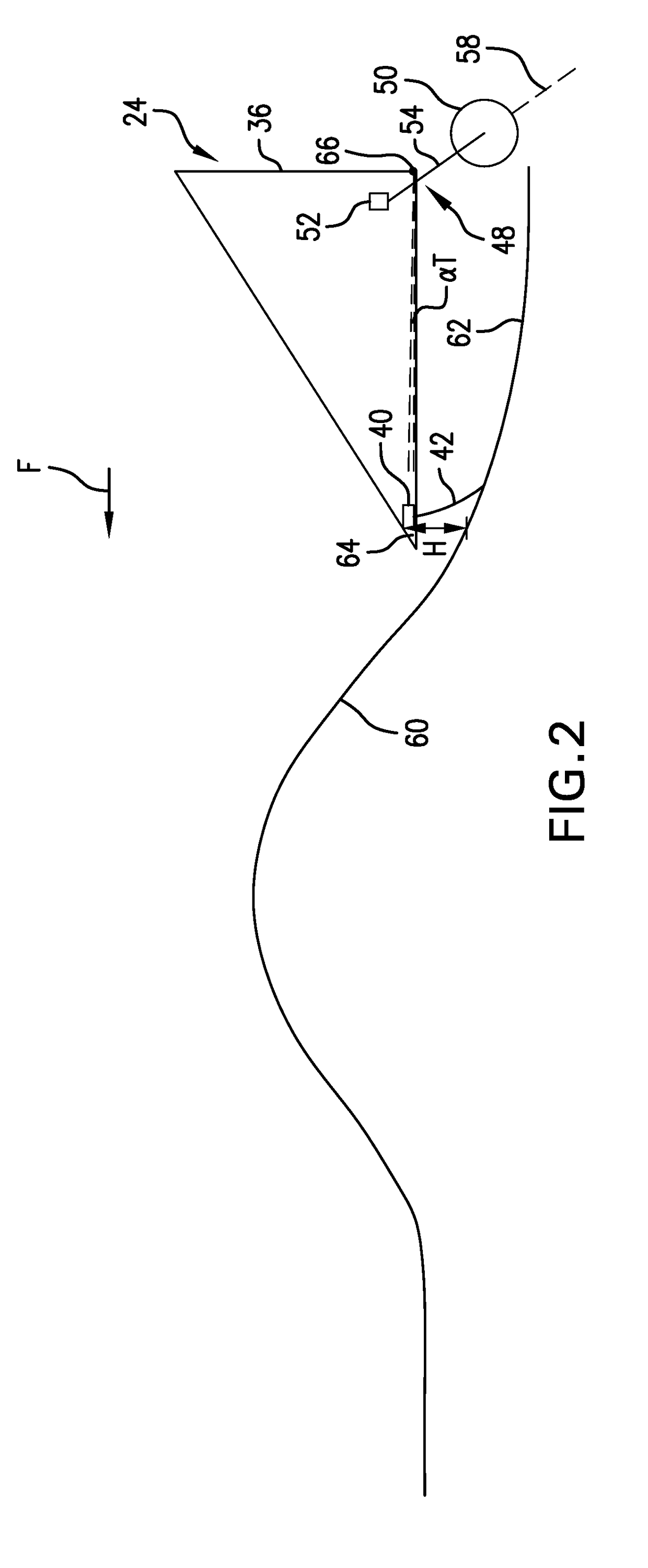
One particular problem that is encountered with such gauge wheels occurs when the header travels over a large terrain irregularity which causes the cutter sensor to leave the ground and the spring of the gauge wheel(s) to fully compress.
The net effect of these simultaneous motions can cause the front of the header to be pointed into the ground as the combine moves forward, forcing the header to dig into the ground and potentially causing significant damage to the header and the combine.

Method used


Image

  • Header height control system with multiple height sensors
  • Header height control system with multiple height sensors
  • Header height control system with multiple height sensors

Examples


Embodiment Construction

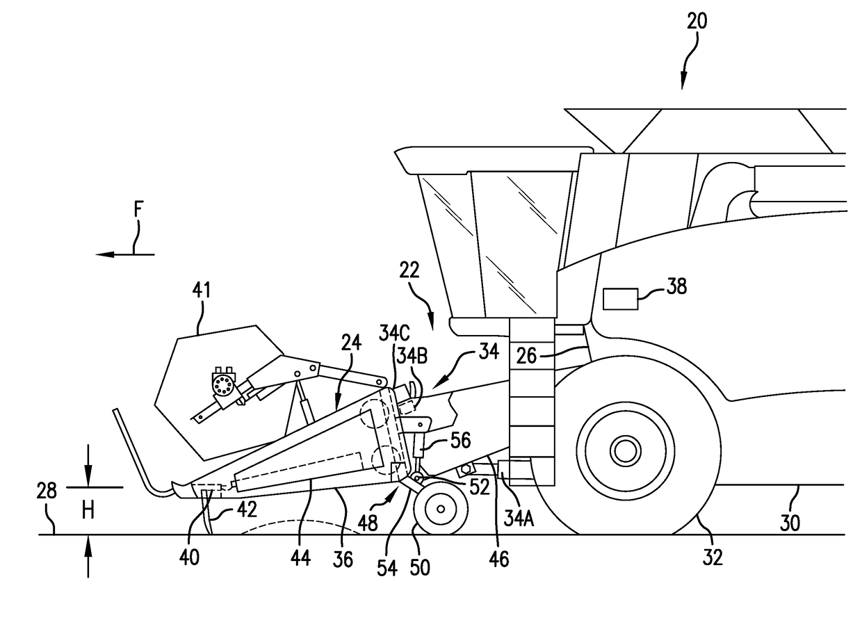
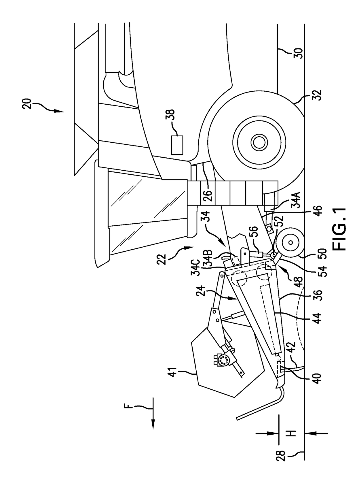
[0028]Referring now to the drawings, and more particularly to FIG. 1, an exemplary embodiment of an agricultural machine 20 formed in accordance with the present invention is shown, including a header height control (HHC) system 22 operable for controlling height and tilting adjustment of a header 24 carried on a front end 26 of machine 20, as machine 20 moves over a ground surface 28, as denoted by arrow F. Harvesting machine 20 is a typical, self-propelled combine harvester having a chassis 30 carrying a conventionally configured and operable engine and power train that drives tracks or wheels 32. The engine can power a cutter 40 of header 24, which can include a conventionally configured and operable sickle cutter, disk cutters, or the like, as well as a reel 41, and gathering apparatus 44, which here is a draper belt system but could be an auger device, all of which are conventionally configured and operable.

[0029]A center region of header 24 is supported on machine 20 by a feed...


PUM


Abstract

An agricultural vehicle includes a chassis and a header system carried by the chassis. The header system includes a frame; a cutter carried by the frame; a cutter sensor associated with the cutter which outputs a cutter height signal; a gauge wheel carried by the frame behind the cutter; a wheel sensor associated with the gauge wheel which outputs a wheel position signal; an actuator system including actuators which can adjust a height and / or a tilt angle of the frame; and a controller electrically coupled to the cutter height sensor, the wheel sensor and the actuator system. The controller is configured to: receive the cutter height signal; receive the wheel position signal; compare the cutter height signal and the wheel position signal to determine a terrain irregularity is present; and activate one or more actuators to adjust the frame in response to determining the terrain irregularity is present.

Description

FIELD OF THE INVENTION[0001]The present invention relates to agricultural vehicles and, more particularly, to agricultural harvesters equipped with a header.BACKGROUND OF THE INVENTION[0002]An agricultural harvester known as a “combine” is historically termed such because it combines multiple harvesting functions with a single harvesting unit, such as picking, threshing, separating and cleaning. A combine includes a header which removes the crop from a field, and a feeder housing which transports the crop matter into a threshing rotor. The threshing rotor rotates within a perforated housing, which may be in the form of adjustable concaves, and performs a threshing operation on the crop to remove the grain. Once the grain is threshed it falls through perforations in the concaves and is transported to a grain pan. From the grain pan the grain is cleaned using a cleaning system, and is then transported to a grain tank onboard the combine. The cleaning system includes a cleaning fan whi...

Claims


Application Information

Patent Timeline
IPC IPC(8): A01D34/00A01D41/127A01D41/14
CPCA01D34/006A01D41/145A01D41/127A01D41/141A01D75/287A01D41/14
Inventor LONG, ZACHARYCOOK, JOEL T.
Owner BLUE LEAF I P
Learn More