Packaging Apparatus with Evacuation Assembly and Packaging Process
- Summary
- Abstract
- Description
- Claims
- Application Information
AI Technical Summary
Benefits of technology
Problems solved by technology
Method used
Image
Examples
first embodiment
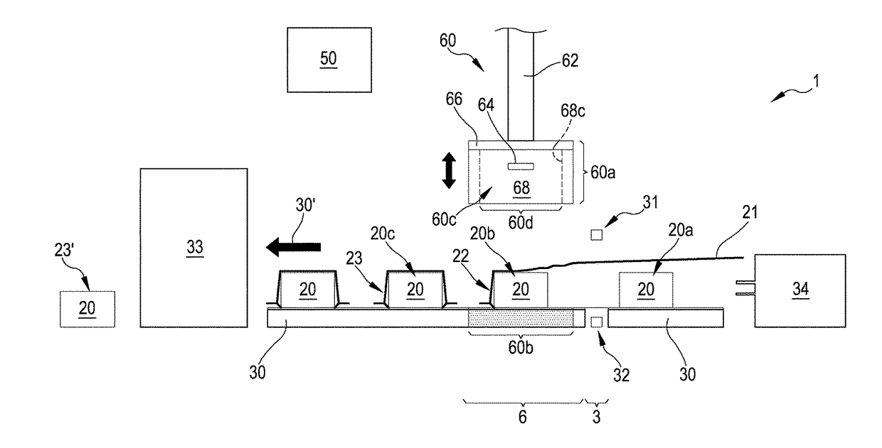
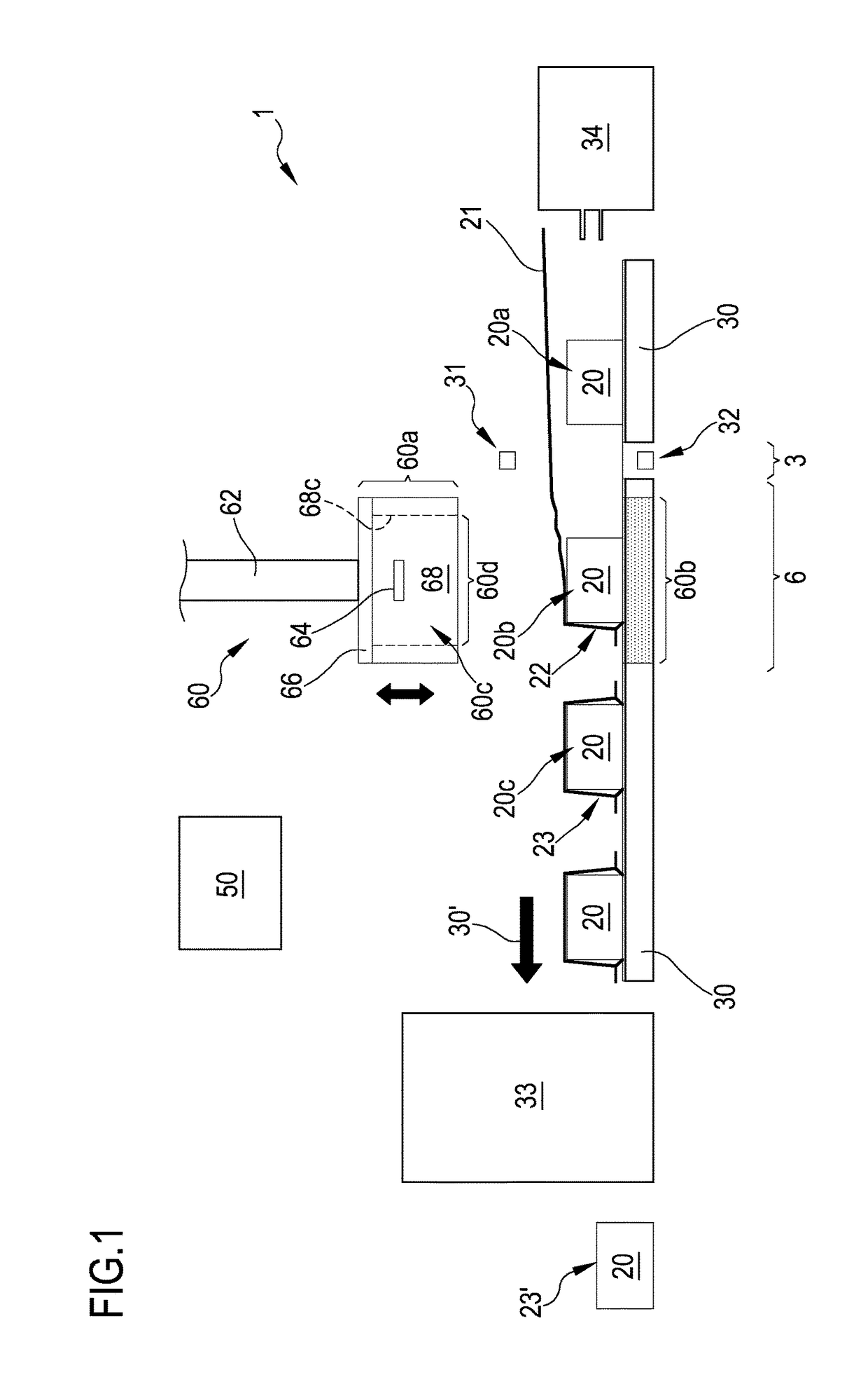
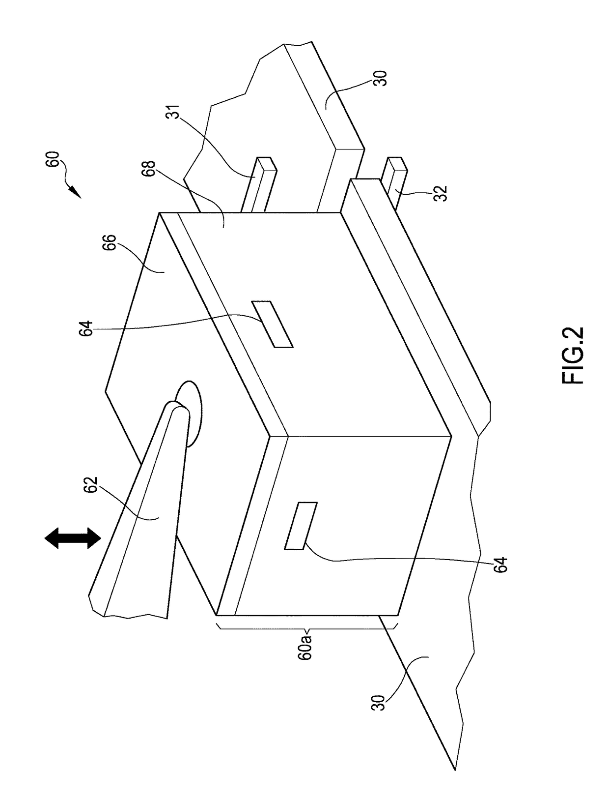
[0078]FIG. 1 schematically shows a packaging apparatus 1 in accordance with the present invention comprising an evacuation assembly 60 located at an evacuating station 6. In general, the packaging apparatus 1 comprises a loading station (not shown), a sealing station 3, an evacuating station 6, and means for moving 30. At the loading station, products 20 are placed into a tubular film 21 or the film is placed around products 20 and continuously sealed along its edges in order to form the tubular film 21 in a manner known in the art. The means for moving 30 are configured to move products 20 situated inside film 21 from the loading station towards and through the sealing station 3 and to the evacuating station 6.
[0079]The products 20 to be packaged may assume different states (20a, 20b, 20c) of being packaged. States 20a, 20b, 20c denote product 20 being in different packaging states. For example, state 20a denotes product 20 positioned inside tubular film 21. State 20b denotes produ...
third embodiment
[0125]FIG. 6B schematically shows magnified details an evacuation assembly 60 in accordance with the present invention, illustrating two different operational states of the evacuation assembly. On the left, bellows 65 of head 60a is shown in an expanded state, which may be present when head 60a is not in contact with support 60b or upon initial contact between head 60a and support 60b, before compression of apron 68. In the expanded state, chamber 60c is either open or closed against support 60b. If chamber 60c is closed against support 60b, it delimits a volume within chamber 60c (e.g. volume 63a as shown in FIG. 4B).
[0126]On the right of FIG. 6B, bellows 65 of head 60a is shown in an compressed state, which may be present when head 60a is in contact with support 60b, after compression of apron 68. In the compressed state, chamber 60c is closed against support 60b and delimits a volume within chamber 60c (e.g. volume 63a′ as shown in FIG. 4C) smaller than volume 63a when apron 68 i...
fourth embodiment
[0134]In accordance with the present invention, evacuation assembly 60 is provided with an adjustable head 60t comprising relatively movable parts 60t-1 and 60t-2. At least one of parts 60t-1 and 60t-2 is movable with respect to the other (or both with respect to one another) in an adjustment direction 61. As can be seen in FIG. 8A-II, part 60t-2 has been moved towards part 60t-1 in order to more closely enclose product 20 placed within head 60t and / or in order to avoid any interference with preceding product 20 (on the left of head 60t). Similarly, as can be seen in FIG. 8A-III, part 60t-2 can also be moved away from part 60t-1 in order to more accommodate a larger product 20 placed within head 60t, while still avoiding any interference with preceding product 20 (on the left of head 60t). In this manner, the size of head 60t can be adapted depending upon size and / or placement of products 20 in order to ensure efficient evacuation.
[0135]FIG. 8B schematically shows an isometric view ...
PUM
| Property | Measurement | Unit |
|---|---|---|
| Fraction | aaaaa | aaaaa |
| Force | aaaaa | aaaaa |
| Force | aaaaa | aaaaa |
Abstract
Description
Claims
Application Information
 - R&D
- Intellectual Property
- Life Sciences
- Materials
- Tech Scout
- Unparalleled Data Quality
- Higher Quality Content
- 60% Fewer Hallucinations
Browse by: Latest US Patents, China's latest patents, Technical Efficacy Thesaurus, Application Domain, Technology Topic, Popular Technical Reports.
© 2025 PatSnap. All rights reserved.Legal|Privacy policy|Modern Slavery Act Transparency Statement|Sitemap|About US| Contact US: help@patsnap.com


