Oven
- Summary
- Abstract
- Description
- Claims
- Application Information
AI Technical Summary
Benefits of technology
Problems solved by technology
Method used
Image

Examples
first embodiment
[0066]FIG. 3 is a view showing a case in which a contaminant collection layer is applied to an oven in accordance with one embodiment of the present disclosure. In FIG. 3, the cooking chamber 20 and the door 100 are shown, and the door 100 is illustrated as being coupled to the cooking chamber 20 for convenience of explanation.
[0067]As shown in FIG. 3, the oven 1 may further include the contaminant collection layer 300.
[0068]The contaminant collection layer 300 may prevent contamination of the cooking chamber 20. Specifically, the contaminant collection layer 300 may keep the cooking chamber 20 clean by adsorbing contaminants generated in a cooking process. In addition, the contaminant collection layer 300 may concentrate contaminants scattered throughout the cooking chamber 20 to improve a user's cleaning convenience.
[0069]The contaminant collection layer 300 may be formed on a part of the inner surfaces of the cooking chamber 20 and the door inner surface 101. Further, the contam...
second embodiment
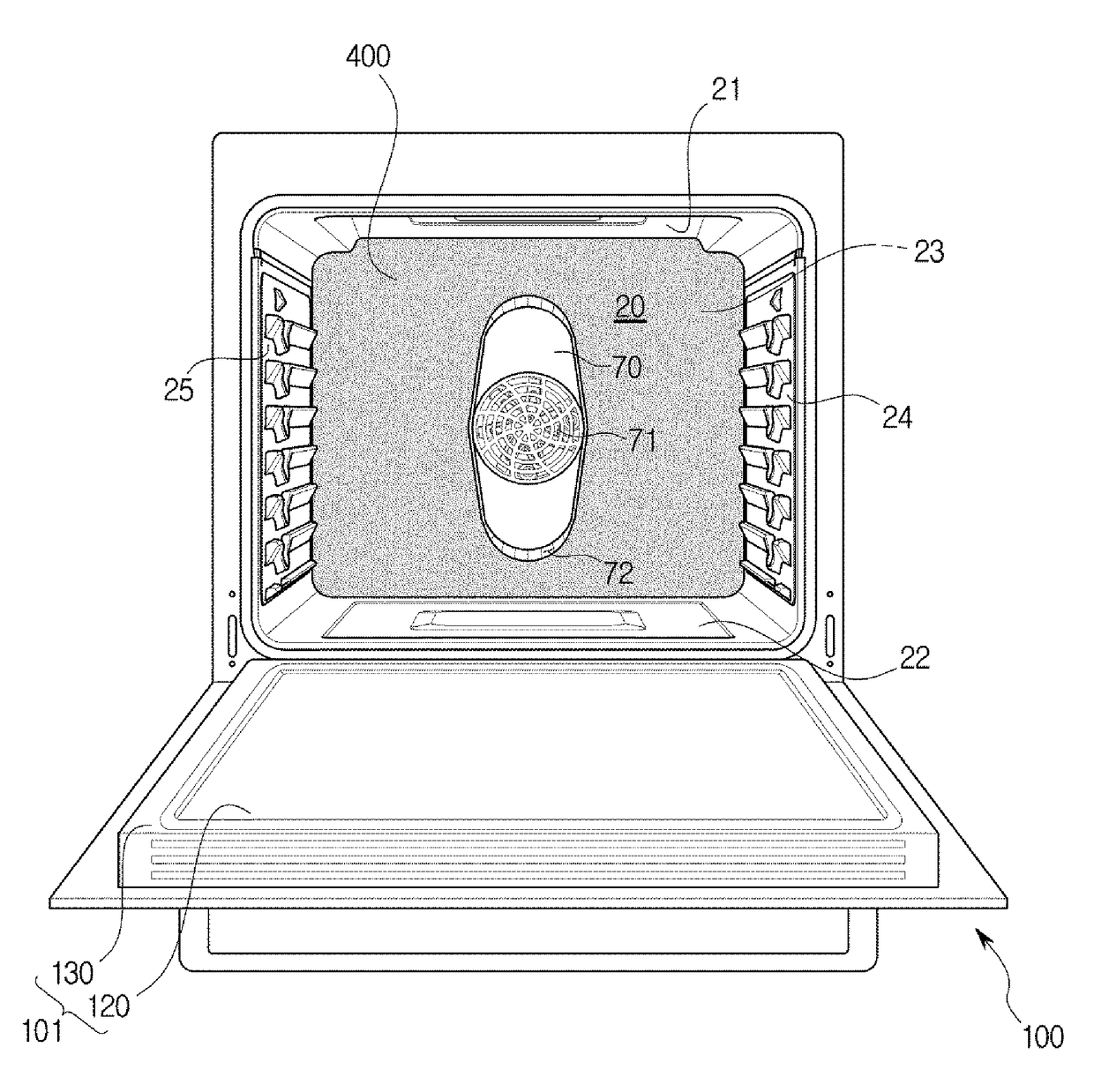
[0074]FIG. 4 is a view showing a case in which a contaminant collection layer is applied to an oven in accordance with one embodiment of the present disclosure. In FIG. 4, the cooking chamber 20 and the door 100 are shown, and the door 100 is illustrated as being coupled to the cooking chamber 20 for convenience of explanation. Descriptions overlapping those of FIG. 1 will be omitted.
[0075]As shown in FIG. 4, the contaminant collection layer 400 may be formed on at least one of the inner surfaces of the cooking chamber 20. Specifically, the contaminant collection layer 400 may be formed on one of the upper surface 21, the lower surface 22, the rear surface 23, the right side surface 24, and the left side surface 25 of the cooking chamber 20.
[0076]The contaminant collection layer 400 according to the second embodiment shown in FIG. 4 may be formed on the rear surface 23 of the cooking chamber 20. Since the contaminant collection layer 400 has excellent adhesion with regard to contam...
third embodiment
[0079]FIG. 5 is a view showing a case in which a contaminant collection layer is applied to an oven in accordance with one embodiment of the present disclosure. In FIG. 5, the cooking chamber 20 and the door 100 are shown, and the door 100 is illustrated as being coupled to the cooking chamber 20 for convenience of explanation. Descriptions overlapping those of FIG. 3 will be omitted.
[0080]As shown in FIG. 5, the contaminant collection layer 500 may be formed on some of the inner surfaces of the cooking chamber 20. Specifically, the contaminant collection layer 500 may be formed on a plurality of surfaces facing each other among the upper surface 21, the lower surface 22, the rear surface 23, the right side surface 24, and the left side surface 25 of the cooking chamber 20. When the contaminant collection layer 500 is formed in this manner, an effect of concentrating contaminants at a desired portion among the inner surfaces of the cooking chamber 20 may be expected. In other words...
PUM
| Property | Measurement | Unit |
|---|---|---|
| Fraction | aaaaa | aaaaa |
| Fraction | aaaaa | aaaaa |
| Fraction | aaaaa | aaaaa |
Abstract
Description
Claims
Application Information
 - R&D Engineer
- R&D Manager
- IP Professional
- Industry Leading Data Capabilities
- Powerful AI technology
- Patent DNA Extraction
Browse by: Latest US Patents, China's latest patents, Technical Efficacy Thesaurus, Application Domain, Technology Topic.
© 2024 PatSnap. All rights reserved.Legal|Privacy policy|Modern Slavery Act Transparency Statement|Sitemap