Image forming apparatus including high voltage generating circuit

Inactive Publication Date: 2018-03-15
CANON KK
View PDF3 Cites 1 Cited by
  • Summary
  • Abstract
  • Description
  • Claims
  • Application Information

AI Technical Summary

Benefits of technology

The patent text describes an image forming apparatus that does not require a circuit to detect the current of the drum ground and can reduce the number of cables needed. This means that the apparatus is simpler and more efficient in its use of electrical power.

Problems solved by technology

This causes an increase in the number of cables between high voltage circuit boards and the control circuit board.

Method used


Image

  • Image forming apparatus including high voltage generating circuit
  • Image forming apparatus including high voltage generating circuit
  • Image forming apparatus including high voltage generating circuit

Examples


Embodiment Construction

Image Forming Apparatus

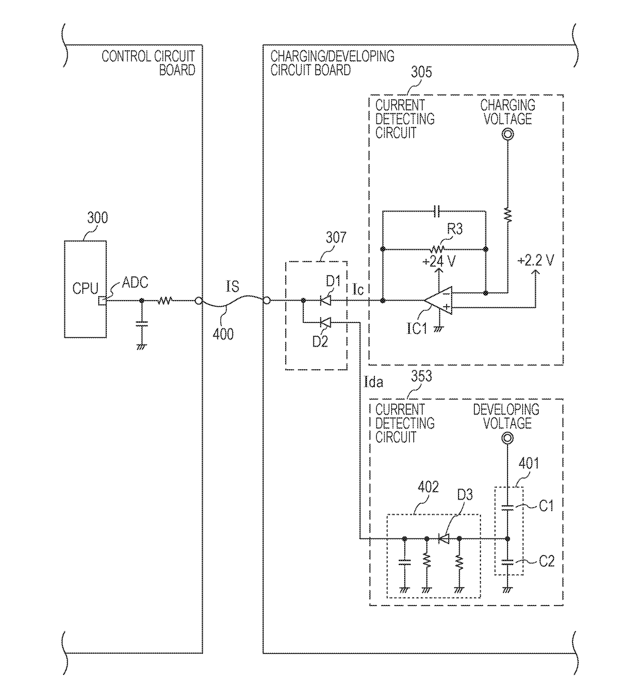
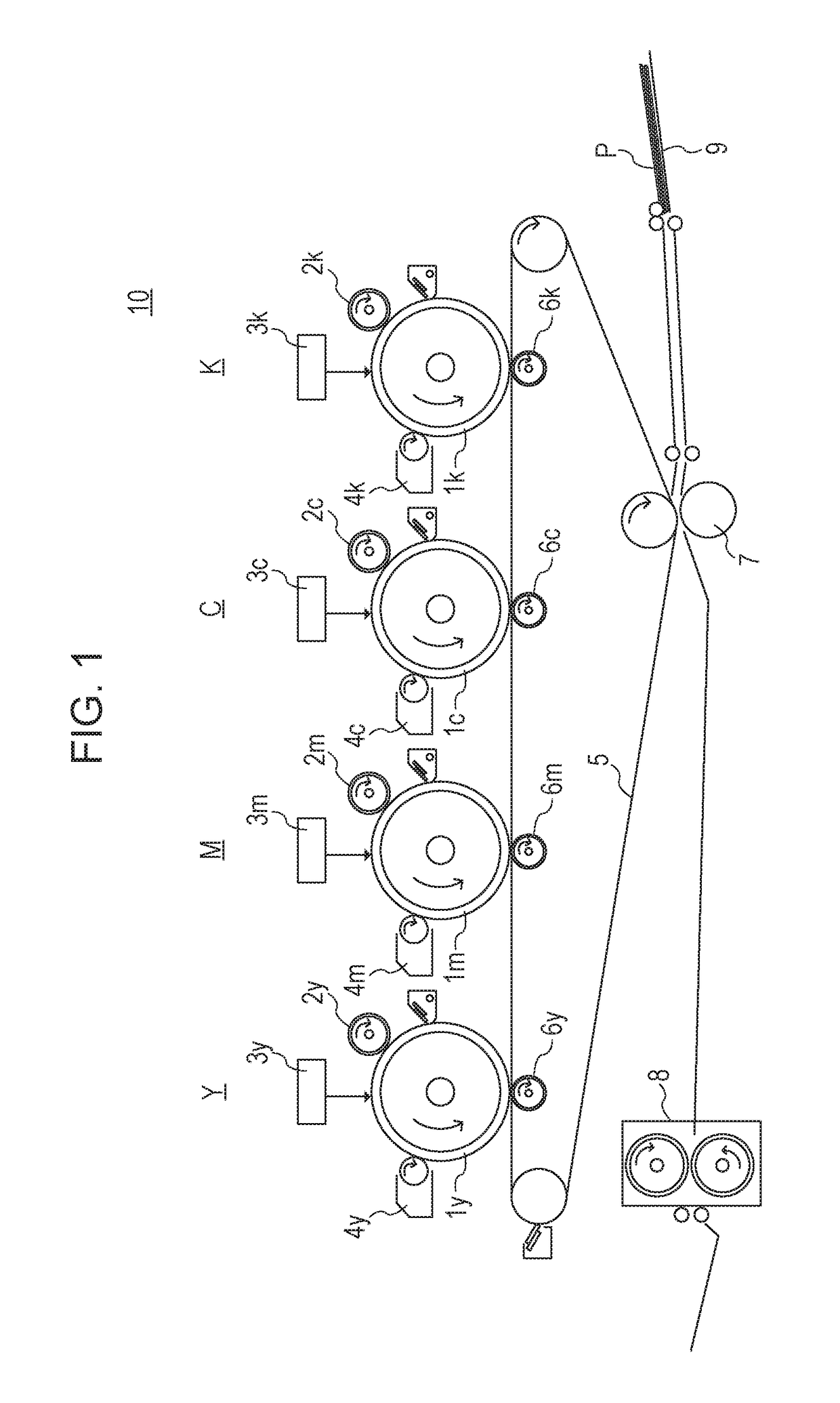
[0015]According to FIG. 1, an image forming apparatus 10 includes four image forming stations by which a multicolor image is formed by superposing toner of four colors of yellow (Y), magenta (M), cyan (C), and black (K). Letters of y, m, c, and k each of which is assigned to an end of a reference sign represent colors of the toner, and the letters of y, m, c, and k are omitted when matters common among the four colors are described. A photoreceptor 1 is a drum-like image carrier which carries an electrostatic latent image and a toner image. A charging roller 2 of a charging device applies a charging voltage to the photoreceptor 1 to uniformly charge a surface of the photoreceptor 1.

[0016]The charging voltage is generated by superposing an alternating current voltage on a direct current voltage. An exposing device 3 is a scanning optical device that has a laser light source and a rotating polygonal mirror. The exposing device 3 modulates laser light in accordan...


PUM


Abstract

An image forming apparatus includes: a first power source that supplies a charging voltage to a charger; a second power source that supplies a developing voltage to a developer; a first current detector that detects a current in the charger; a second current detector that detects a current in the developer; an OR circuit to which a first detection signal of the first current detector and a second detection signal of the second current detector are input; and a controller that determines an error related to the first power source or the photoreceptor or an error related to the second power source or the developer on the basis of an output signal of the OR circuit, which is output correspondingly to a level of the first detection signal or a level of the second detection signal.

Description

BACKGROUND OF THE INVENTIONField of the Invention[0001]The aspect of the embodiments relates to an image forming apparatus including a high voltage generating circuit.Description of the Related Art[0002]In an image forming apparatus of an electrophotographic system, a high voltage circuit board that supplies a charging voltage to a charging roller and a high voltage circuit board that supplies a developing voltage to a developing sleeve of a developer are provided. A control circuit board connected to the high voltage circuit boards controls the high voltage circuit boards and detects an error related to the high voltage circuit boards. According to an invention described in Japanese Patent Laid-Open No. 2002-333812, a method of detecting a charging error by detecting a value of a current flowing through a charging roller is proposed. According to an invention described in Japanese Patent Laid-Open No. 2009-122208, a detecting circuit that detects an excess current flowing through a...

Claims


Application Information

Patent Timeline
IPC IPC(8): G03G15/02H04N1/00
CPCG03G15/0266H04N1/00904H04N1/00899H04N1/00076G03G15/065H04N1/00037G03G15/0283G03G15/00G03G21/00G03G15/55G03G15/553G03G15/75
Inventor NAKAJIMA, HIROHISA
Owner CANON KK
Why Eureka
Try Eureka