

Stable two component spray foam compositions containing hydrohaloolefin propellant or blowing agent
- Summary
- Abstract
- Description
- Claims
- Application Information
AI Technical Summary
Benefits of technology
Problems solved by technology
Method used
Image


Examples
examples
[0091]The following non-limiting examples are provided to further illustrate the present invention.
examples 1-4
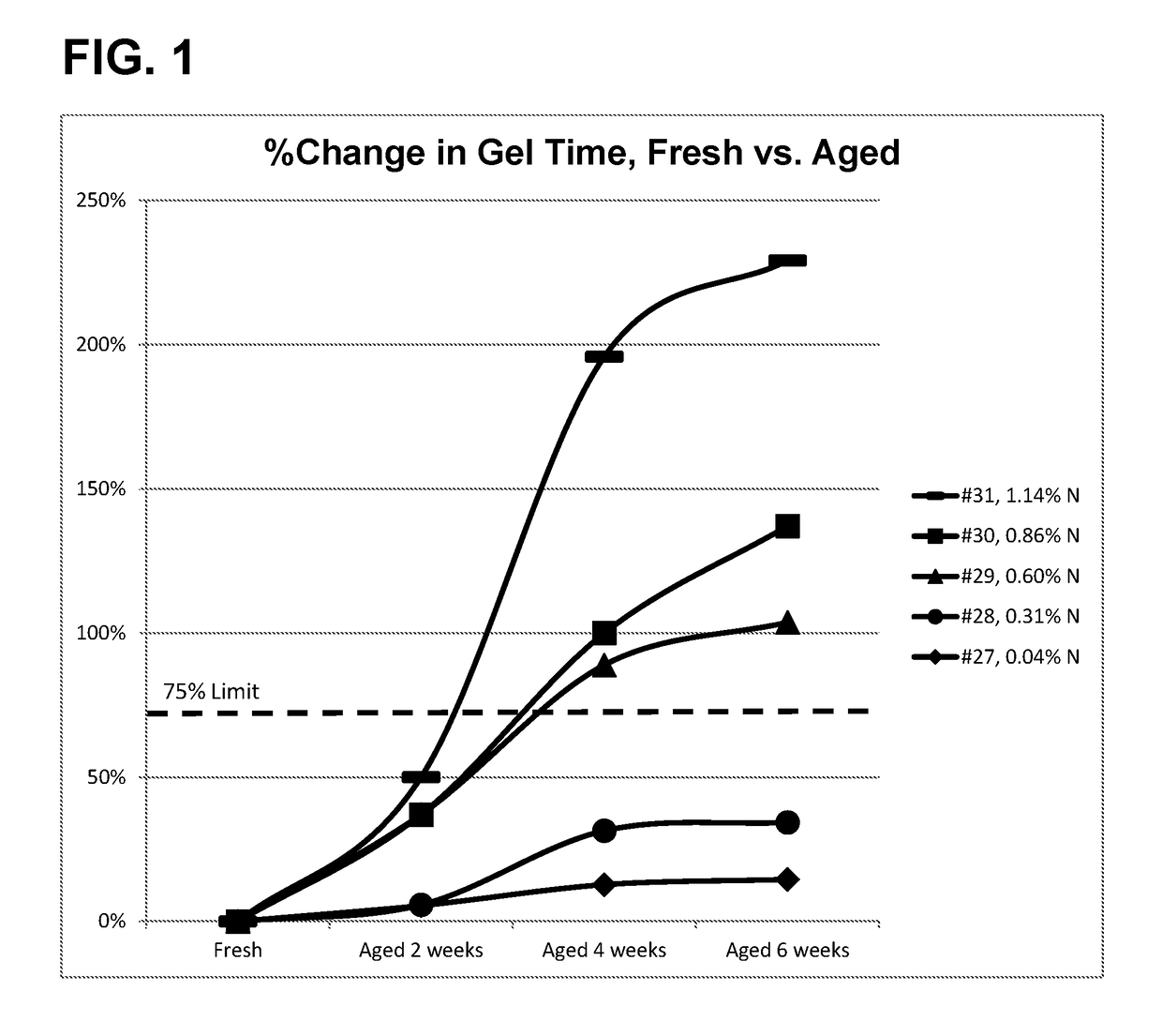
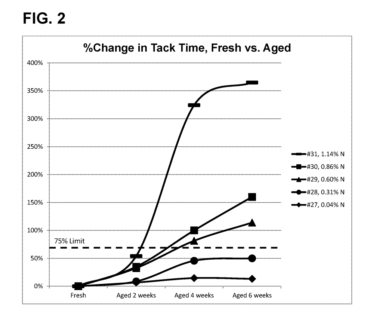
[0092]The two component low pressure polyurethane spray foam-forming compositions were prepared from the components as listed in the tables below. The shelf-life stability of “B”-side component for a two component spray foam system is determined based on its chemical reactivity changes when the “B” side component is aged under either actual storage conditions or accelerated storage conditions for certain period of time. Both gel-time and tack-free time can be used to represent the chemical reactivity of the system. A stable system as defined herein undergoes no more than 75% change in chemical reactivity after being aged, while also maintaining its foam quality and density, as compared to the composition at the time of manufacture as measured under the same conditions. When the chemical reactivity comprises gel time, the composition can exhibit an increase in gel time of not more than 75% when the composition is stored at a temperature of 120° F. (49° C.) for a time period of 2, 4, ...
examples 5-9
[0096]Compositions were prepared as described above in Examples 1-4. The compositions of Examples 5-9 contained less amino polyol as compared to the compositions of Examples 1-4. The compositions of Examples 5 and 6 included amine and metal catalysts, while the compositions of Examples 7-9 included only metal catalysts. The compositions of Examples 5 and 6 which included the amine catalysts had severe shelf-life instability in accelerated storage testing at 120° F. (49° C.), as evidenced by significant % change in gel time or tack free time as compared to fresh samples. Foam density data collected indicate small changes in foam density for these examples. The compositions of Examples 7-9 were stable and had desirable shelf life, as evidenced by no significant % change in gel time or tack free time as compared to fresh samples.
PUM
| Property | Measurement | Unit |
|---|---|---|
| Percent by mass | aaaaa | aaaaa |
| Percent by mass | aaaaa | aaaaa |
| Temperature | aaaaa | aaaaa |
Abstract
Description
Claims
Application Information