Bolt type probe

Active Publication Date: 2018-03-22
CHUNGHWA PRECISION TEST TECH
View PDF1 Cites 10 Cited by
  • Summary
  • Abstract
  • Description
  • Claims
  • Application Information

AI Technical Summary

Benefits of technology

[0006]In order to solve the above-mentioned technical problems, an object of the present disclosure is to provide a probe including a specific conductive structure, which is connected between a probe head and a probe tail for transmitting current and signals. Moreover, since the conductive structure has a certain sized cross-section area, the “needle burning” caused by the current exceeding the maximum withstand current of the conductive stru

Problems solved by technology

Recently, with electronic products developing towards precision and versatility, the ch

Method used


Image

  • Bolt type probe
  • Bolt type probe
  • Bolt type probe

Examples


Embodiment Construction

[0026]The structure and the technical means adopted by the present disclosure to achieve the above and other objects can be best understood by referring to the following detailed description of the preferred embodiments and the accompanying drawings.

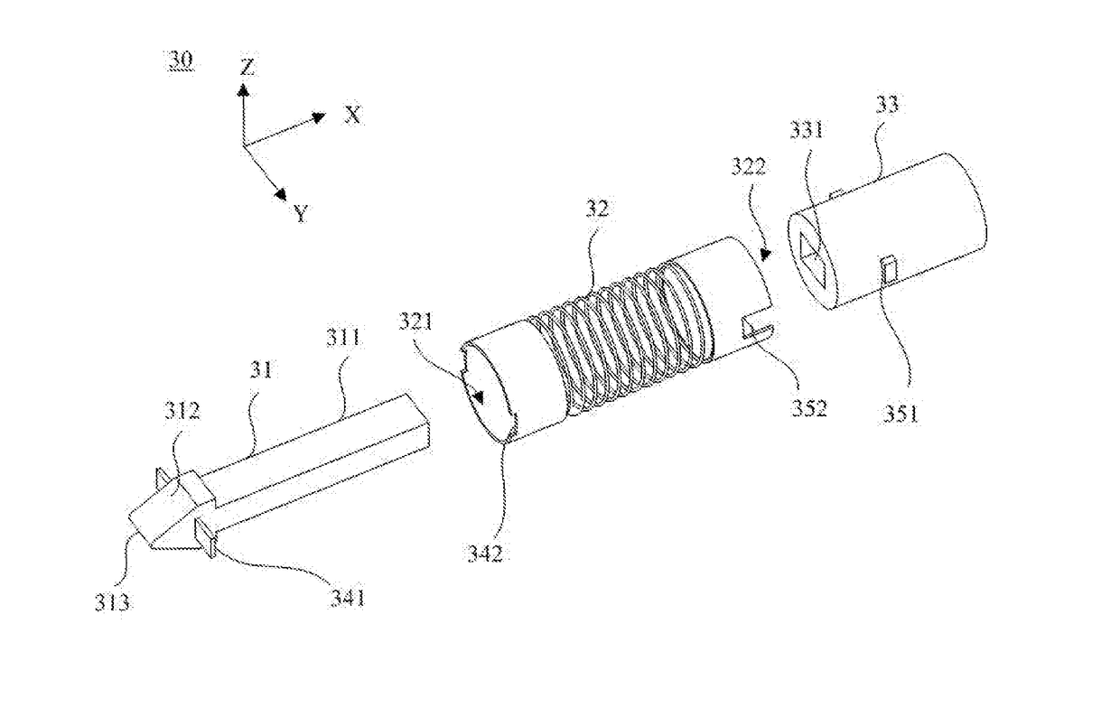
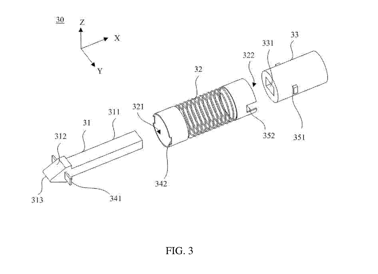
[0027]FIG. 3 depicts a stereoscopic exploded diagram of a bolt type probe according to a preferred embodiment of the present disclosure. The bolt type probe 30 is used for assembling with a probe device of a probe card. The bolt type probe 30 includes a probe head 31, an elastic element 32, and a probe tail 33. The elastic element 32 is connected with the probe head 31 and the probe tail 33. The probe head 31 and the probe tail 33 are disposed in alignment with the same axis (i.e., X axis). The elastic element 32 is made of elastic material, and the bolt of the probe head is surrounded by the elastic material. The probe head 31 includes a probe head section 312 and a bolt 311 connected with the probe head section 312. Moreover, the probe...


PUM


Abstract

A bolt type probe is provided, including a probe head having a bolt at one end thereof, a probe tail having a bolt hole corresponding to the bolt, an elastic element connected with the probe head and the probe tail. At least one portion of the bolt of the probe head is inserted in the bolt hole of the probe tail, and the bolt is moved relative to the bolt hole along with a movement of the elastic element.

Description

FIELD OF THE DISCLOSURE[0001]The present disclosure relates to a bolt type probe, and more particularly to a probe used in a probe card.BACKGROUND[0002]Recently, with electronic products developing towards precision and versatility, the chip structure of integrated circuits used in electronic products tends to be complicated. At the time of manufacture, in order to ensure the electrical quality of the wafer, wafer-level measurement is performed before packaging the wafer. The current measuring method for testing wafers needs a probe card. According to the type of probes, probe card type includes a cantilever probe card and a vertical probe card. In use, the probes of the probe card are directly electrically contacted with pads or bumps of the wafer, and then an electrical signal is transmitted into a tester through a circuit board of the probe card, such that a testing signal from the tester is transmitted into the wafer, or an output signal from the wafer can be received by the tes...

Claims


Application Information

Patent Timeline
IPC IPC(8): G01R1/067G01R31/28
CPCG01R1/06722G01R31/2886G01R1/06733G01R1/06738G01R1/06761
Inventor HSIEH, CHIH-PENG
Owner CHUNGHWA PRECISION TEST TECH
Why Eureka
Try Eureka