Female terminal and connector

Active Publication Date: 2018-03-22
SUMITOMO WIRING SYST LTD
View PDF7 Cites 13 Cited by
  • Summary
  • Abstract
  • Description
  • Claims
  • Application Information

AI Technical Summary

Benefits of technology

[0008]A contacting protrusion may be provided on the metal plate in an innermost layer of the closely folded structure and may project inward of the rectangular tubular box for contacting a mating male terminal inserted into the rectangular tubular box. The contacting protrusion and the lance locking portion may be positioned to overlap in an inserting direction of the male terminal. In this configuration, the lance locking portion and the

Problems solved by technology

Thus, if a strong pulling force acts on the terminal, the locking lance may deform the retaining projection and it may not be possible to exhibit a sufficient lockin

Method used


Image

  • Female terminal and connector
  • Female terminal and connector
  • Female terminal and connector

Examples


Embodiment Construction

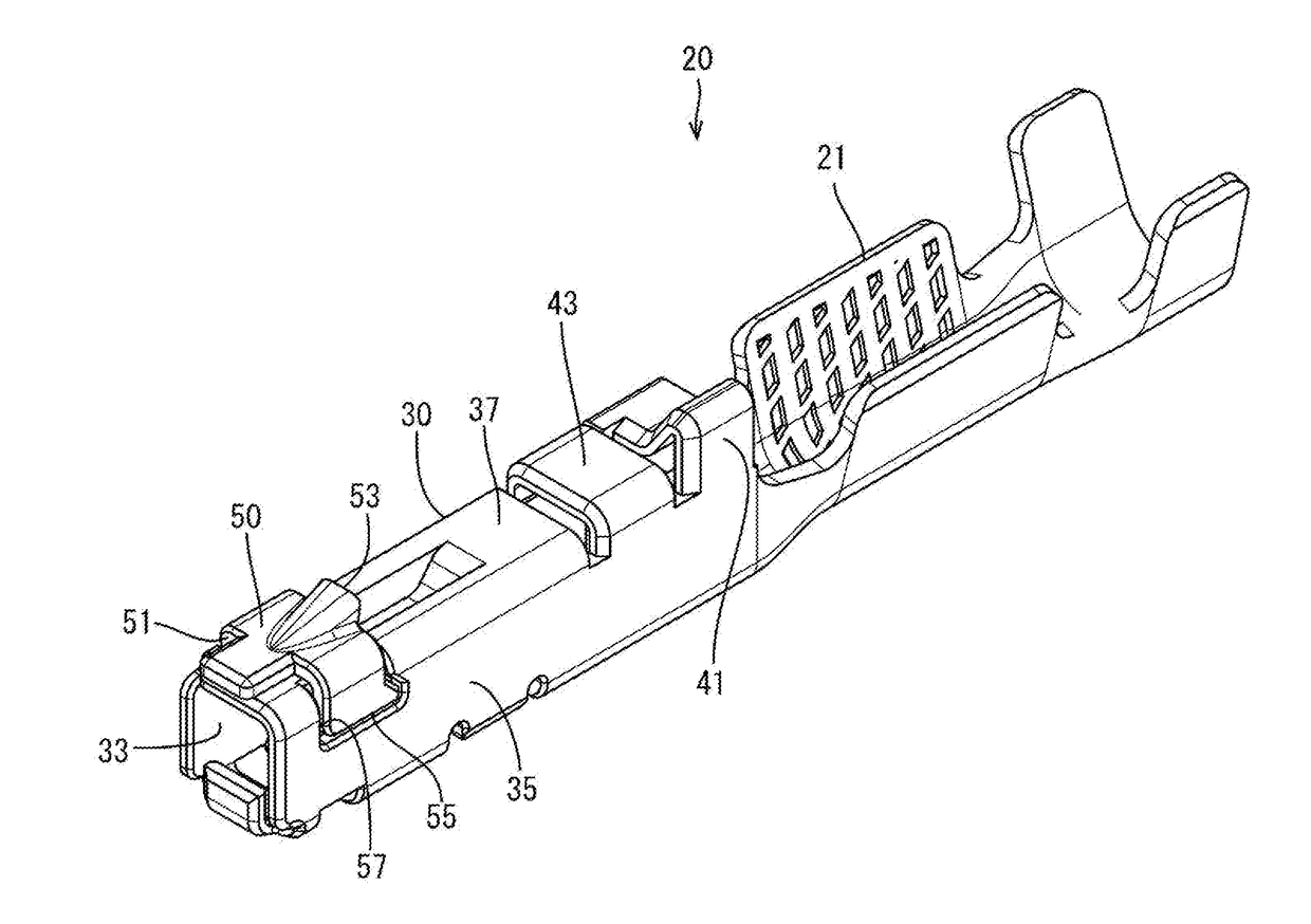
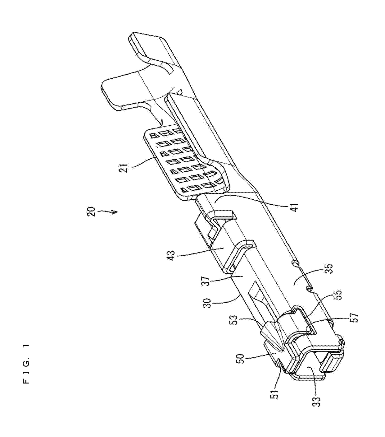
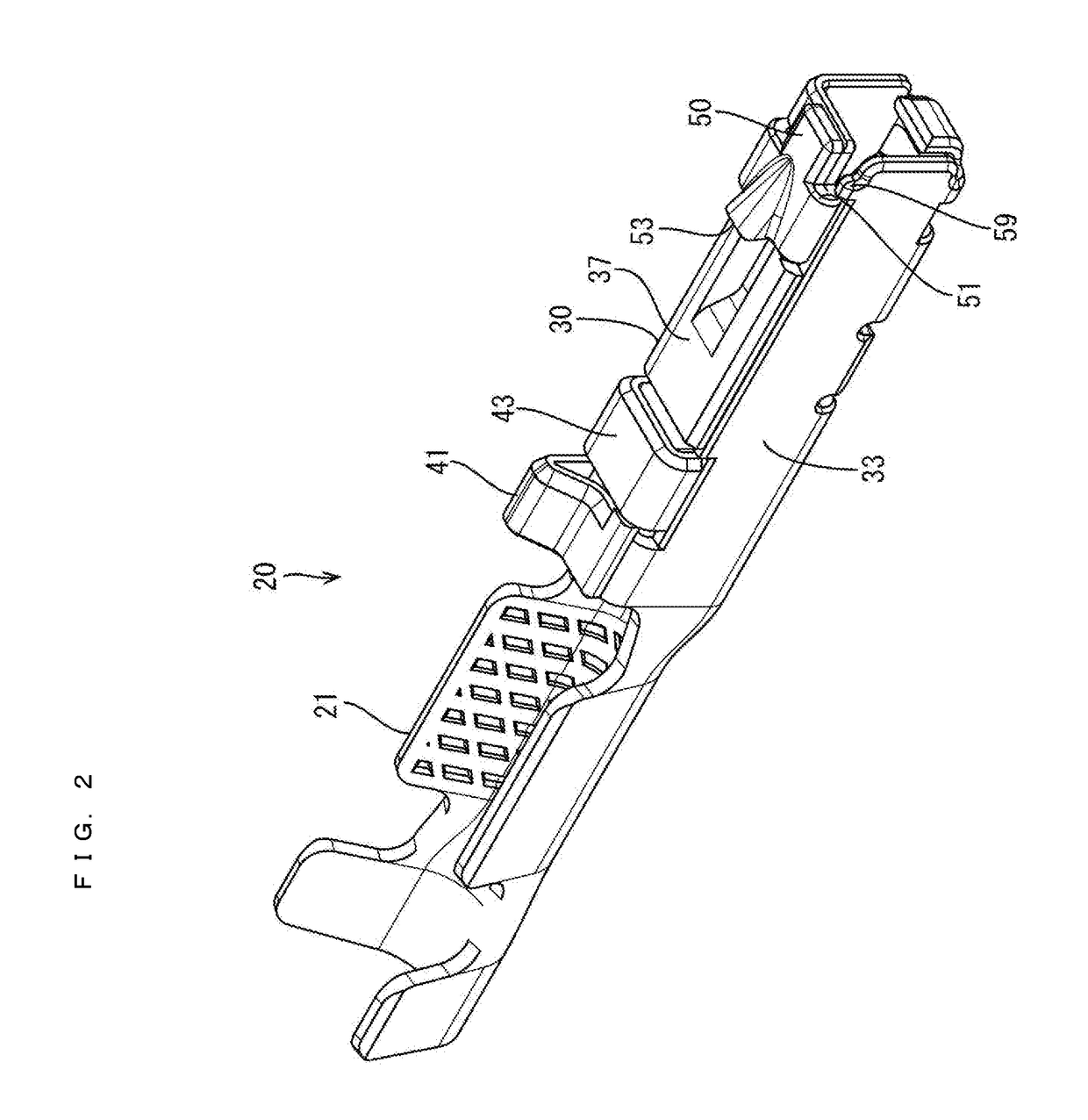
[0018]An embodiment is described with reference to FIGS. 1 to 8.

[0019]A connector C of this embodiment includes a connector housing 10 and a female terminal 20. In the following description, a left side (connecting direction to a mating male terminal) and a right side of FIG. 5 are referred to as a front side and a rear side concerning a front-rear direction. Further, vertical and lateral directions are based on FIG. 3.

[0020]The connector housing 10 is made of synthetic resin and, as shown in FIG. 7, is provided internally with a cavity 11 extending in the front-rear direction. The female terminal 20 is insertable into the cavity 11. A terminal insertion opening is open in the rear end of this cavity 11, and the female terminal 20 is inserted through this terminal insertion opening. A locking lance 13 is provided on an upper surface in the cavity 11 and is cantilevered forward in the same direction as an inserting direction of the female terminal 20. The locking lance 13 is deflecta...


PUM


Abstract

A female terminal (20) has a rectangular tubular box (30) with an outwardly bulging lance locking portion (53). The female terminal (20) is inserted into a cavity (11) of a connector housing (10) and retained by the lance locking portion (53) being locked by a locking lance (13) in the cavity (11). A first wall (37) of the rectangular tubular box (30) has a closely folded structure obtained by folding the metal plate (70) into a U shape. The lance locking portion (53) is formed on the metal plate (70) in an outermost layer of the closely folded structure, and a first deformation restricting portion (55) to be engaged with a second wall (35) adjacent to the first wall (37) is provided on an end part of the metal plate (70) in the outermost layer on a side opposite to a U-shaped folded portion (51).

Description

BACKGROUND1. Field of the Invention[0001]The invention relates to a female terminal and a connector using this female terminal.2. Description of the Related Art[0002]A connector used at an electrical connection position generally has a terminal accommodated in a cavity of a connector housing and retained by a locking lance formed in the cavity. Japanese Unexamined Patent Publication No. 2002-190342 discloses a female terminal with a rectangular tubular box and a retaining projection that bulges out on a wall of the rectangular tubular box. A cut is formed in the front surface of the retaining projection, and the tip of the locking lance is fit into the cut to retain the terminal fitting in the cavity.[0003]The terminal fitting of this type is manufactured by press-working a metal plate material. The use of a thinner metal plate material may be required for a reduction of material cost, weight saving and the like. However, if a plate thickness is reduced, the rigidity of the retainin...

Claims


Application Information

Patent Timeline
IPC IPC(8): H01R13/422H01R24/20H01R4/18
CPCH01R13/4223H01R13/6271H01R24/20H01R4/185H01R13/10H01R13/432H01R13/113H01R43/16
Inventor GOTO, YUICHI
Owner SUMITOMO WIRING SYST LTD
Why Eureka
Try Eureka