Method for allocating resources for supporting plurality of wireless communication modes in wireless communication system, and device for same

a wireless communication system and resource allocation technology, applied in the field of wireless communication systems, can solve the problems of data request latency of 1 ms, new tti structure and new types of symbols have not been suggested, and achieve the effect of enhancing time-frequency resource efficiency

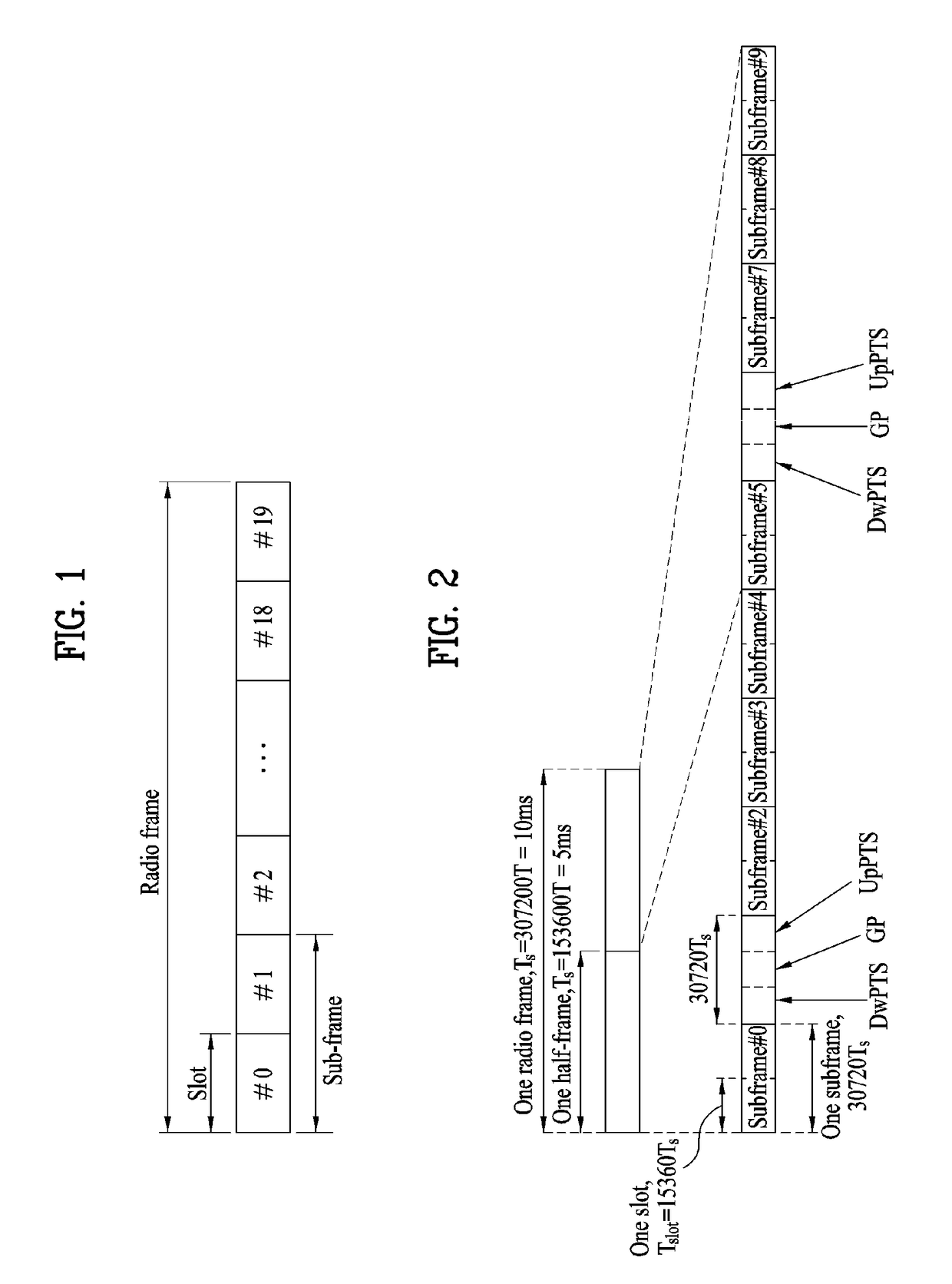
Active Publication Date: 2018-03-22
LG ELECTRONICS INC
View PDF5 Cites 7 Cited by
  • Summary
  • Abstract
  • Description
  • Claims
  • Application Information

AI Technical Summary

Benefits of technology

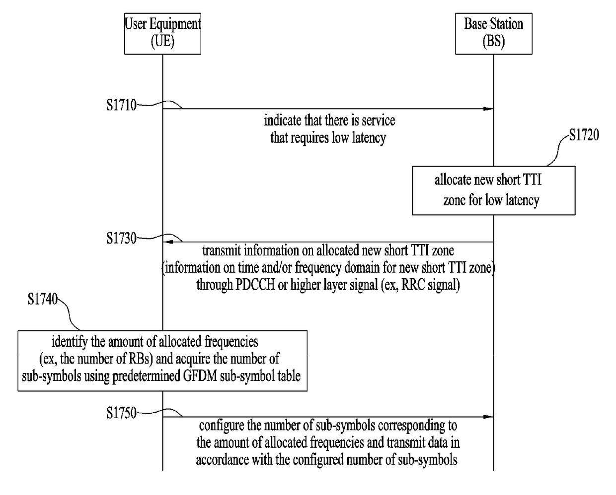
[0012]The present invention suggests a method for configuring sub-symbols based on a new waveform for a reference signal allocation scheme of a TDM mode when a short TTI is configured for low latency communication, whereby time-frequency resource efficiency may be enhanced. Also, a system according to configuration of sub-symbols based on such a new waveform may be multi...

Problems solved by technology

However, the frame structure having a TTI of 1 ms according to the related art has a problem in that data request lat...

Method used


Image

  • Method for allocating resources for supporting plurality of wireless communication modes in wireless communication system, and device for same
  • Method for allocating resources for supporting plurality of wireless communication modes in wireless communication system, and device for same
  • Method for allocating resources for supporting plurality of wireless communication modes in wireless communication system, and device for same

Examples


embodiment 1

e Number of Guard Subcarriers is Set to the Number of Sub-Symbols of GFDM Symbols −1 (Nguard=Msub−1)

[0107]First of all, to multiplex OFDM symbols and GFDM symbols, the OFDM symbols and the GFDM symbols should maintain orthogonality with each other. If a raised cosine filter roll-off factor is set to 1, guard subcarriers should be given as much as the number of maximum Msub−1. For this orthogonality, the case that Nguard is set to Msub−1 may be considered, and this case corresponds to the case that the most guard subcarriers are given. In this case, the Equation 4 may be expressed by the following Equation 5.

Nsc×NRS−Nsc / Msub×NRS−(Msub−1)×Nsym>0  [Equation 5]

[0108]By the Equation 5, the number of sub-symbols of GFDM symbols is determined as expressed by the following Equation 6.

1MsubNsc×NRS) / Nsym and aliquot of Msub=Nsc  [Equation 6]

[0109]To obtain a maximum value, the following Equation 7 that a differential value of the Equation 5 is 0 is obtained as follows.

(Nsc×NRS) / Msub2−Msub×Nsy...

embodiment 2

sub>guard Includes a Function Related to Msub (Nguard=f(Msub))

[0116]Generally, in case of GFDM, a pulse shape may be controlled depending on filter application as shown in FIG. 14. Therefore, for orthogonality, Nguard may be set to be shorter than Msub−1. Therefore, the above Equation 4 for determining the number of sub-symbols of GFDM symbols may be corrected as expressed by the following Equation 10, and the number of sub-symbols of GFDM symbols may be determined in accordance with the Equation 10.

Nsc×NRS−Nsc / Msub×NRS−f(Msub)×Nsym>0  [Equation 10]

[0117]The number of sub-symbols of GFDM symbols is a value of Msub that satisfies the above Equation 10.

[0118]It is considered that a raised cosine filter (roll-off factor=β) is used in a pulse shape of GFDM as shown in FIG. 14. In this case, for orthogonality, the value of Nguard may be set to be shorter than Msub−1. That is, repetition of the frequency domain with OFDM symbols equivalent to M / 2(1+β) is generated. Therefore, guard subcar...


PUM


Abstract

A method for a base station to allocate resources for supporting a plurality of wireless communication modes in a wireless system according to the present invention comprises the steps of: allocating, using frequency-division multiplexing, a first zone composed of orthogonal frequency division multiplexing (OFDM) symbols and a second zone composed of generalized frequency division multiplexing (GFDM) symbols on time and frequency domains; and allocating a predetermined number of guard subcarriers to the boundary between the first zone and the second zone, wherein the predetermined number is determined on the basis of the number of sub-symbols of the GFDM symbols of the second zone.

Description

TECHNICAL FIELD[0001]The present invention relates to a wireless communication system, and more particularly, to a method for allocating resources for supporting a plurality of wireless communication modes in a wireless communication system and a device for the same.BACKGROUND ART[0002]A 3GPP LTE (3rd Generation Partnership Project Long Term Evolution) system has been designed in a frame structure having a transmission time interval (TTI) of 1 ms, and its data request latency time for a video application is 10 ms. However, the future 5G technology requires data transmission of lower latency due to the advent of a new application such as real-time control and tactile internet, and it is expected that 5G data request latency will be lowered to reach 1 ms.[0003]However, the frame structure having a TTI of 1 ms according to the related art has a problem in that data request latency of 1 ms cannot be fulfilled. 5G aims to provide data latency reduced as much as about 10 times as compared...

Claims


Application Information

Patent Timeline
IPC IPC(8): H04L5/00H04W72/04H04L5/12
CPCH04L5/0035H04W72/0446H04L5/12H04L5/0092H04L5/0007H04L5/0053H04L27/2602H04L5/0048H04L5/0094H04L27/26035H04L27/2603
Inventor LEE, SANGRIMKO, HYUNSOOCHOI, KUKHEONNOH, KWANGSEOKKIM, DONGKYU
Owner LG ELECTRONICS INC
Why Eureka
Try Eureka