

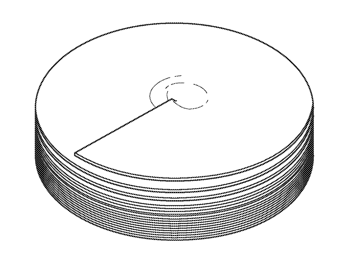
3D manufacturing using multiple material deposition and/or fusion sources simultaneously with single or multi-flute helical build surfaces
a technology of helical build surface and fusion source, which is applied in the direction of additive manufacturing with liquids, manufacturing tools, manufacturing processes, etc., can solve the problems of complex systems, the existing system that uses the x-y plane build surface cannot use multiple materials at the same time, and the technique can only use similar materials
- Summary
- Abstract
- Description
- Claims
- Application Information
AI Technical Summary
Benefits of technology
Problems solved by technology
Method used
Image

Examples
Embodiment Construction
[0047]In the following detailed description, reference is made to the accompanying drawings, which form a part hereof. In the drawings, similar symbols typically identify similar components, unless context dictates otherwise. The illustrative embodiments described in the detailed description, drawings, and claims are not meant to be limiting. Other embodiments may be utilized, and other changes may be made, without departing from the spirit or scope of the subject matter presented here. It will be readily understood that the aspects of the present disclosure, as generally described herein, and illustrated in the figures, can be arranged, substituted, combined, and designed in a wide variety of different configurations, all of which are explicitly contemplated and made part of this disclosure.
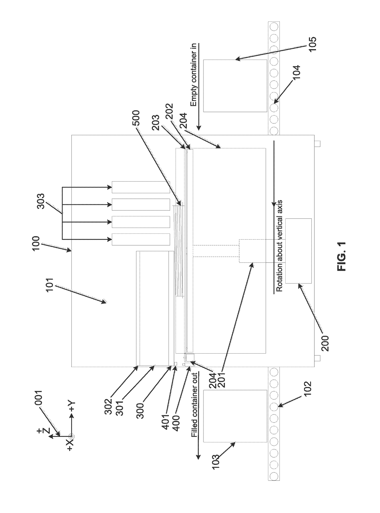
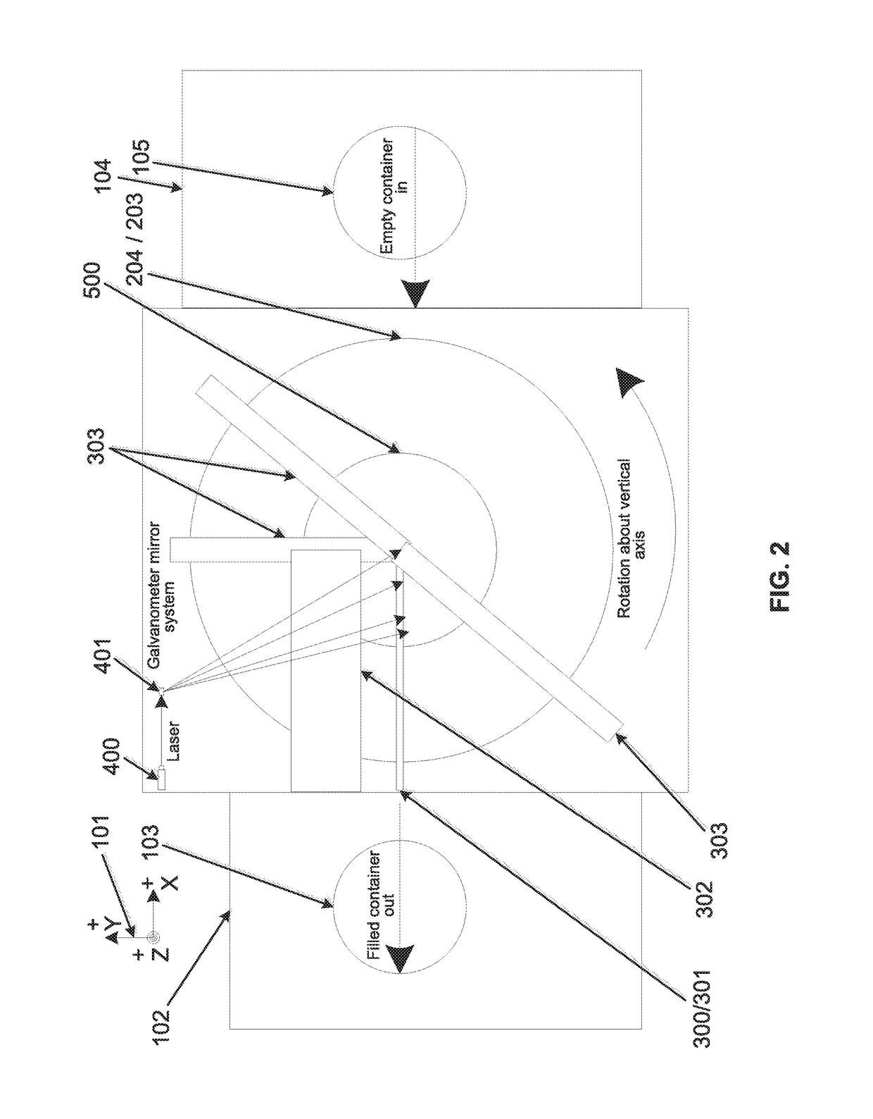
[0048]Described herein are methods and an apparatus adapted for improving the speed of production and quality (resolution) of the free-form manufacture of complex systems using multiple three-di...
PUM
| Property | Measurement | Unit |
|---|---|---|
| Speed | aaaaa | aaaaa |
Abstract
Description
Claims
Application Information