Supercharge Your Innovation With Domain-Expert AI Agents!

Vehicular structure

a technology of a panel and a structure, applied in the field of a vehicle structure, can solve the problems of difficulty in keeping the weight low, and achieve the effects of reducing the vibration of the panel member, enhancing the stiffness with respect to vibration, and reducing weigh

Active Publication Date: 2018-03-29
TOYOTA JIDOSHA KK
View PDF0 Cites 3 Cited by
  • Summary
  • Abstract
  • Description
  • Claims
  • Application Information

AI Technical Summary

Benefits of technology

The present invention concerns a vehicular structure that can reduce vibration while achieving weight reduction. The solution involves using a panel member made of resin with reinforcing fibers, which is joined to the vehicle body in a way that supports the panel member all around. The panel member has a bulging shape, where both front and back surfaces of the panel member bulge out, to enhance its stiffness against vibration. Additionally, the number of layers of continuous fibers is increased towards the central portion of the panel member to further enhance its stiffness. This structure helps to effectively reduce vibration of the panel member, and provides a lightweight solution for vehicles.

Problems solved by technology

However, it is difficult to keep the weight low in a configuration that relies only on a high-density viscoelastic material layer to reduce vibration as in the above technology, so there is room for improvement from the standpoint of achieving a reduction in weight.

Method used


Image

  • Vehicular structure
  • Vehicular structure
  • Vehicular structure

Examples


embodiment

Operation of Embodiment

[0040]Next, the operation of the above-described embodiment will be described.

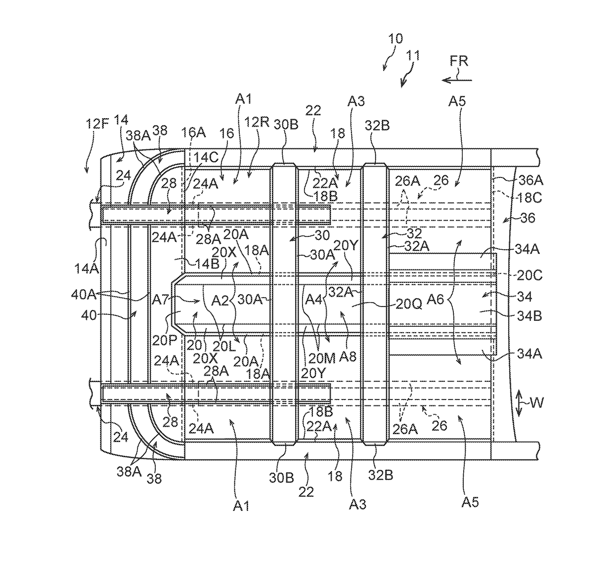
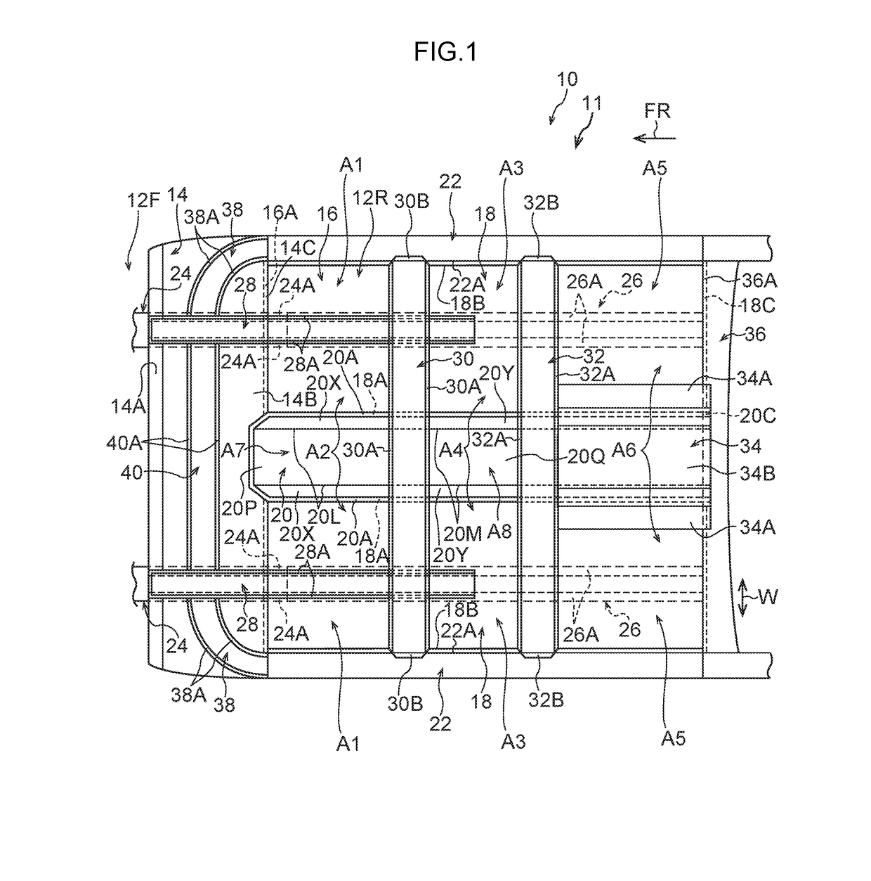
[0041]According to the above-described configuration, the vehicle body floor panels 18 shown in FIG. 1 are each configured by resin including reinforcing fibers, so the vehicle body floor panels 18 each have a configuration advantageous to weight reduction. Each peripheral portion of the first areas A1 to the sixth areas A6 of the vehicle body floor panels 18 has its four sides as seen in a vehicle plan view joined (restrained) to, and is supported all the way around by, the vehicle body. For this reason, in a case where the first areas A1 to the sixth areas A6 vibrate, those areas tend to elastically deform in the vibration direction an increasingly greater extent from the peripheral end portion to the central portion (i.e., the portion tending to become the antinode of the vibration) with the restrained four sides serving as the node of the vibration. To address this, in the presen...

modified examples of embodiment

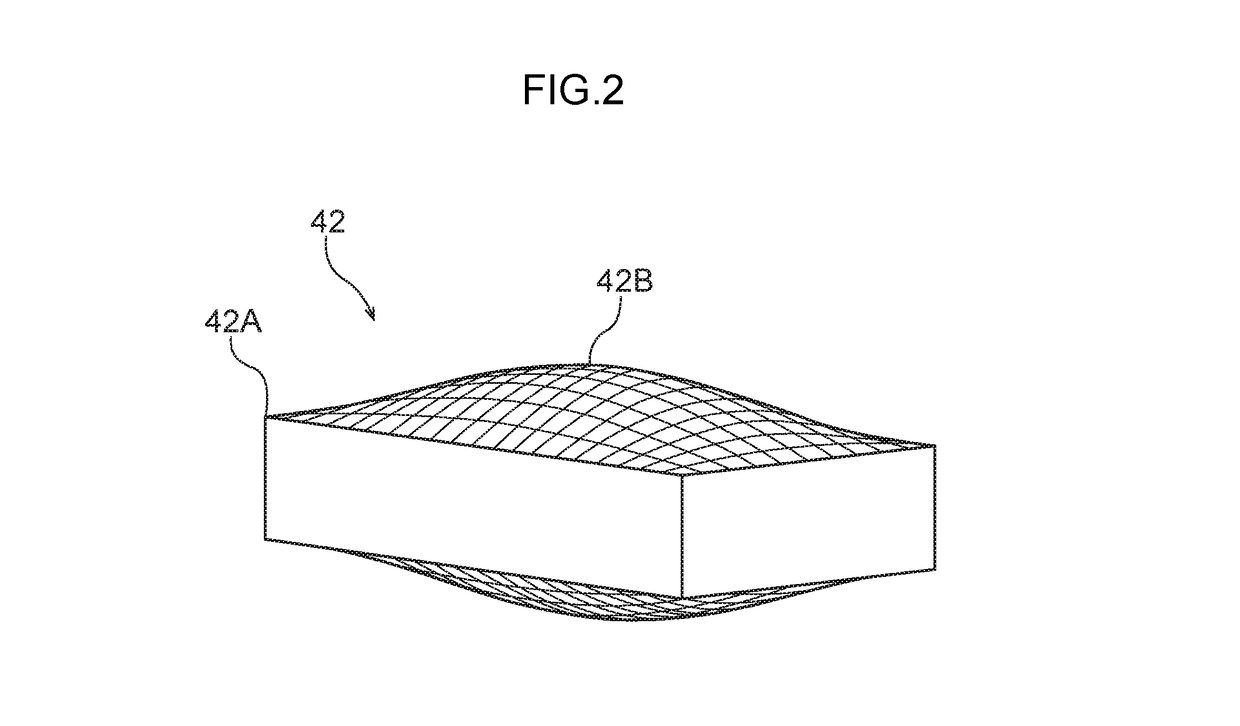
[0050]It should be noted that, as a modified example of the above-described embodiment, the panel member (in the above-described embodiment, the vehicle body floor panels 18 and the floor tunnel panel 20) may also be a panel member where the reinforcing fibers are continuous fibers (as an example, continuous carbon fibers), plural layers of the continuous fibers are disposed on top of each other as seen in the thickness direction of the panel member, and the number of layers of the continuous fibers is set greater in the central portion than in the peripheral end portion in the site having the bulging shape (see FIG. 2). According to this kind of configuration, in the site having the bulging shape, stiffness on the central portion with respect to vibration is effectively enhanced by the layers of the continuous fibers, so vibration of the panel member is even more effectively reduced. It should be noted that vibration of the panel member can be reduced even more if the direction of ...


PUM

PropertyMeasurementUnit
vehicular structureaaaaaaaaaa
areaaaaaaaaaaa
thicknessaaaaaaaaaa

Abstract

There is provided a vehicular structure including (i) a vehicular panel member configured by resin including reinforcing fibers, and (ii) a joined portion of a vehicle body that supports, all the way around, a peripheral portion of a predetermined area of the panel member and to which the peripheral portion of the predetermined area is joined, wherein the panel member has a bulging shape where both front and back surfaces of the panel member bulge out such that the thickness of the panel member gradually becomes thicker from a peripheral end portion to a central portion within the predetermined area supported all the way around by the joined portion

Description

CROSS-REFERENCE TO RELATED APPLICATION[0001]This application claims priority under 35 USC 119 from Japanese Patent Application No. 2016-190228 filed on Sep. 28, 2016, the disclosure of which is incorporated by reference herein.BACKGROUNDTechnical Field[0002]The present disclosure relates to a vehicular structure.Related Art[0003]Technologies for reducing vibration of a panel member are known. For example, see Japanese Patent Application Laid-open (JP-A) No. 2004-291408, U.S. Patent Application Publication No. 2010 / 0196736, and JP-A No. 2005-023691. Of these, JP-A No. 2004-291408 discloses a technology relating to a vibration damping composite material where a fiber-reinforced composite material layer and a gelated viscoelastic material layer are disposed in layers and integrated.[0004]However, it is difficult to keep the weight low in a configuration that relies only on a high-density viscoelastic material layer to reduce vibration as in the above technology, so there is room for im...

Claims


Application Information

Patent Timeline
Patent Type & Authority Applications(United States)
IPC IPC(8): B62D29/04B62D25/20B62D25/14B32B5/12B32B5/14B32B5/26B60R13/08
CPCB62D29/043B62D25/20B62D25/14B32B5/12B32B5/145B29L2031/3055B60R13/0815B32B2605/08B32B2307/102B29L2031/3017B32B5/26B62D29/04
Inventor AIZAWA, KAIOKANO, MASAYUKISASAKI, SHO
Owner TOYOTA JIDOSHA KK
Features
  • R&D
  • Intellectual Property
  • Life Sciences
  • Materials
  • Tech Scout
  • Unparalleled Data Quality
  • Higher Quality Content
  • 60% Fewer Hallucinations
Learn More