Rotary actuator

a technology of rotary actuators and actuators, applied in the direction of friction gearings, belts/chains/gearings, friction gearings, etc., can solve the problem that rotary actuators cannot be formed thinly so much

Active Publication Date: 2018-03-29
SMC CORP
View PDF7 Cites 6 Cited by
  • Summary
  • Abstract
  • Description
  • Claims
  • Application Information

AI Technical Summary

Benefits of technology

[0005]According to the present invention, the bodies and the extended portions secure a sufficient pressure receiving area, so that it is possible to sufficiently secure a necessary thrust for a rack displacing operation. Further, the space shielded from the cylinder hole is formed between the pair of pistons, so that it is possible to use this space to arrange members such as piston position detection magnets or a wear ring. Consequently, it is possible to provide an effect of realizing the small and thin rotary actuator.

Problems solved by technology

Therefore, the rotary actuator cannot be formed thinly so much.

Method used


Image

  • Rotary actuator
  • Rotary actuator
  • Rotary actuator

Examples


first embodiment

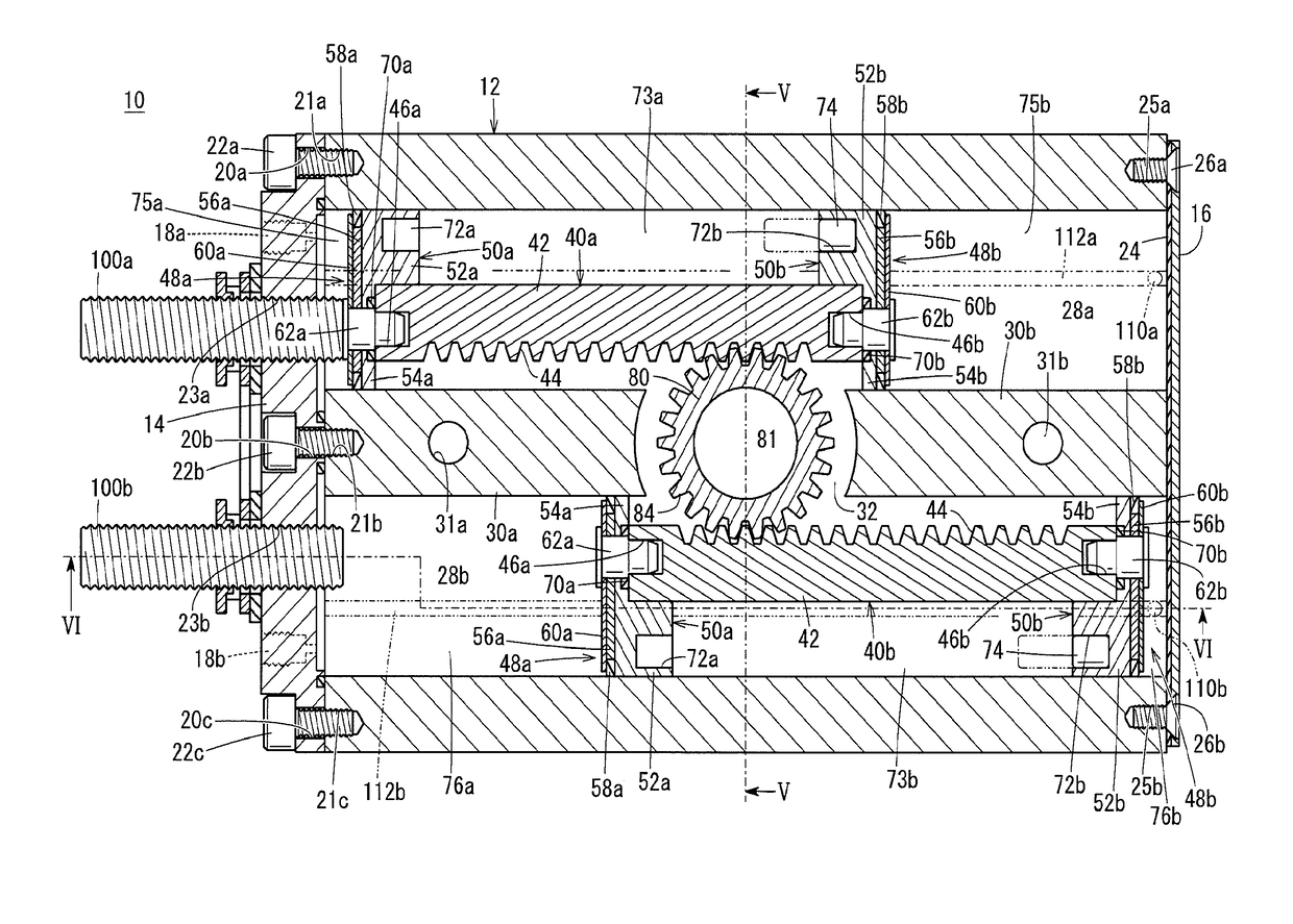
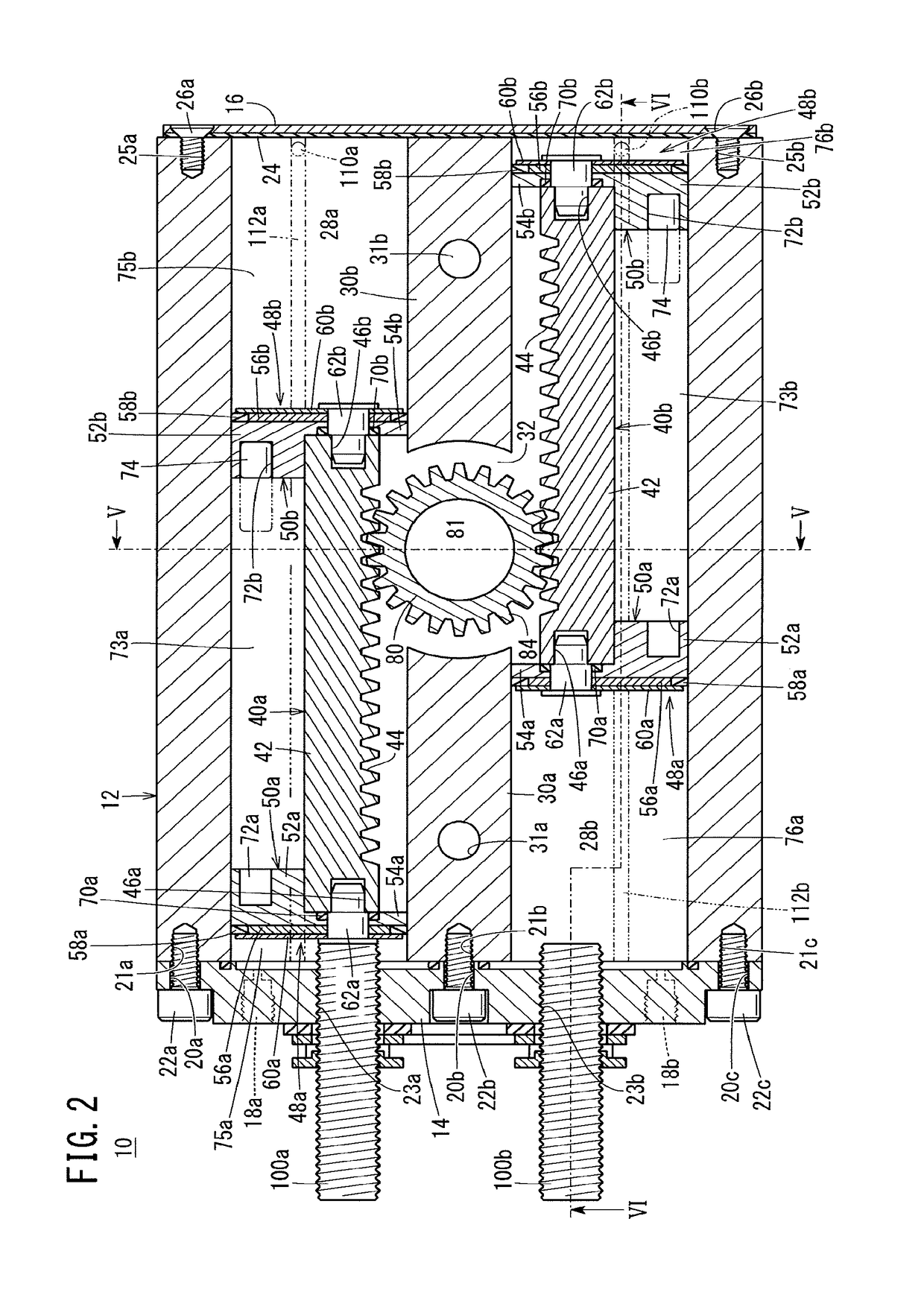
[0014]The rotary actuator according to the present invention includes a pair of linear actuating mechanisms in parallel inside a cylinder body as described in detail below. Each linear actuating mechanism includes a pair of pistons, and a rack that is displaced by a reciprocating operation of the pistons. Further, the rotary actuator includes a pinion that is turned by a reciprocating operation of the rack. A rotating operation of the pinion is configured to, for example, rotate a table arranged outside the cylinder body.

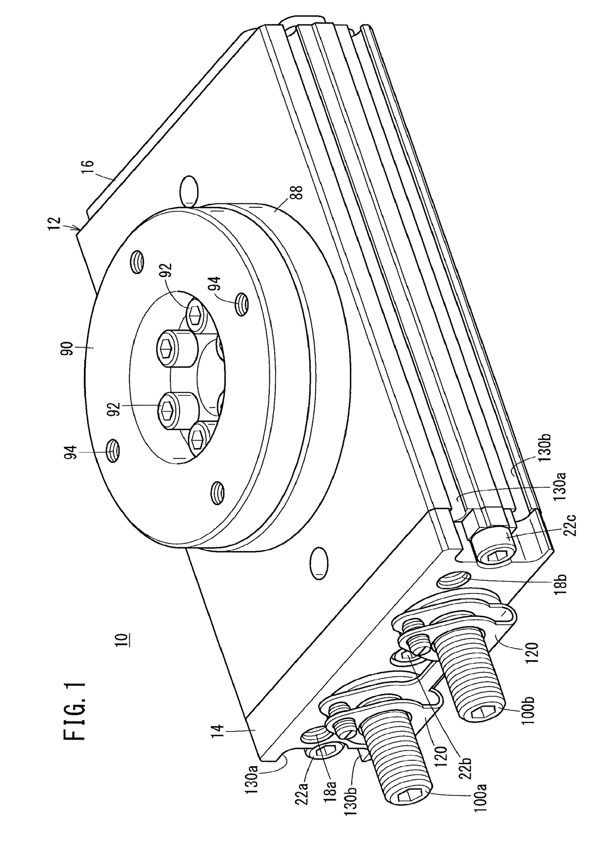
[0015]These components will be more specifically described. In FIG. 1, a reference numeral 10 denotes a rotary actuator according to the first embodiment. This rotary actuator 10 includes a cylinder body 12 that is made of aluminum alloy and is formed in a flat rectangular shape. An opening portion is formed in one end surface perpendicular to a longitudinal direction of the cylinder body 12, and is closed by a first cover 14. An opening portion is formed in another...

second embodiment

[0055]The rotary actuator 200 is basically configured as described above. Next, a function and an effect of the rotary actuator 200 will be described.

[0056]Tubes for supplying and discharging a pressure fluid such as compressed air are connected to the ports 18a, 18b via the connectors that are not shown. When the compressed air is supplied from the port 18a, the piston main body 222a on a side of the first cover 206 becomes a pressure receiving portion, and presses the rack 42 toward the second cover 208. As a result, the rack 42 is displaced toward the second cover 208, and air in the cylinder chamber between the piston main body 222b and the second cover 208 is compressed, and is discharged from the port 18b to a tube that is not shown.

[0057]During the displacement, the pinion 80 that enmeshes with the teeth 44 of the rack 42 rotates in the clockwise direction in FIG. 7. As a result, an end position of the piston main body 222b on a side of the second cover 208 is detected by th...


PUM


Abstract

A rotary actuator (10) is provided with a linear activation mechanism (40a) that causes a pinion (80) to rotate, and a cylinder body (12) in which a cylinder hole (28a) is formed. The linear activation mechanism (40a) comprises a rack (42) on which a plurality of teeth (44) that mesh with the pinion (80) are provided, and pistons (48a, 48b). The pistons (48a, 48b) are each provided with a piston main body (50a, 50b) that has a shape corresponding to that of the cylinder hole (28a). Each of the piston main bodies (50a, 50b) comprises a body (52a, 52b) and an extension section (54a, 54b). The ends of the rack (42) are connected to the extension sections (54a, 54b) of the set of pistons (48a, 48b), and a space (73a) shielded from the cylinder hole (28a) is formed between the bodies (52a, 52b) of the set of pistons (48a, 48b). The linear activation mechanism (40b) is also configured similarly.

Description

TECHNICAL FIELD[0001]The present invention relates to a rotary actuator. In more detail, the present invention relates to a rotary actuator that can turn a workpiece or a table under an action of a pinion that enmeshes with a rack by supplying and discharging a fluid and causing a piston attached to the rack to perform a reciprocating operation.BACKGROUND ART[0002]Japanese Laid-Open Patent Publication No. 2008-157289 (referred to as Patent Document 1 below) discloses a technical idea of a rotary actuator of this type. An object of the invention disclosed in this Patent Document 1 is to realize a thin rotary actuator. However, according to a specific configuration of this invention, a pressure receiving surface that receives a fluid to actuate a piston has a substantially circular shape. Therefore, the rotary actuator cannot be formed thinly so much.SUMMARY OF INVENTION[0003]A main object of the present invention is to provide a rotary actuator that is small and thin compared to the ...

Claims


Application Information

Patent Timeline
Patent Type & Authority Applications(United States)
IPC IPC(8): F15B15/06F15B15/28F16H19/04
CPCF15B15/065F15B15/2861F16H19/04F15B15/1419F15B15/24F15B15/2807F15B15/1404F15B2211/7058F15B15/063
Inventor MAGARIBUCHI, MITSUNORIKOBAYASHI, TAKAAKI
Owner SMC CORP
Why Eureka
Try Eureka