Universal lighting sconce

a universal lighting and sconce technology, applied in the direction of fixed installation, lighting and heating equipment protection devices, etc., can solve the problems of installation cost, installation cost, inconvenient maintenance, etc., and achieve the effect of low inventory and high adaptability

Inactive Publication Date: 2018-03-29
SOUTHWIRE CO LLC
View PDF0 Cites 9 Cited by
  • Summary
  • Abstract
  • Description
  • Claims
  • Application Information

AI Technical Summary

Benefits of technology

[0007]The advantage of the present invention is that it allows contractors or installers the ability to adapt the lighting sconce to any existing junction box or device ring without having to own a large inventory of sconces with mounting plates of all shapes and sizes or have to look for different mounting stored elsewhere. The contractor is able to keep a lower inventory due to the high adaptability and storage of the lighting sconce.
[0008]In one example embodiment of the present invention, the lighting sconce comprises a lighting sconce junction box having at least a first opening configured to receive a light socket and having at least a second opening configured to receive a conduit. A conduit is coupled to the lighting sconce junction box and projects away from the lighting sconce junction box. The conduit is adapted to receive electrical wiring and relay the electrical wiring to the lighting sconce junction box and a light socket. This embodiment further comprises a cover plate removably or movably coupled to the lighting sconce junction box configured to cover a portion of the lighting sconce junction box or open to expose an inside compartment of the lighting sconce junction box. The lighting sconce junction box is further dimensioned to accommodate at least one mounting plate positioned within the inside compartment. Additionally, the at least one mounting plate is adapted to be removably coupled to an end of the conduit opposite the lighting sconce junction box.
[0009]In some embodiments, the lighting sconce further comprises at least one divider positioned within the inside compartment configured to divide the inside compartment into at least two compartments. The divider may comprise an internal wall or partial wall, netting, posts, pegs, screws or rods to apportion the inside compartment.
[0010]In another example embodiment where the divider is a wall, the divider acts to divide the lighting sconce junction box into at least two separate compartments. At least one of the at least two separate compartments is configured to harness electrical wiring for the light socket and isolate from the second compartment of the at least two separate compartments, while the second compartment is used to store additional mounting plates, tools and / or mounting hardware.
[0011]In yet another example embodiment, an elongated member projects from the lighting sconce junction box and is configured such that a mounting plate may be removably coupled thereto for storage of the mounting plate.
[0012]In another example embodiment, the lighting sconce junction box and the mounting plate may be configured to removably magnetically engage each other such that the mounting plate may be stored on the inside or outside of the lighting sconce junction box when not in use.

Problems solved by technology

Further, the junction box may or may not have an attached device ring for fixture mounting.
This is tedious and cost inefficient because the installer needs to ensure in advance that he has the proper temporary sconce for the job, and depending on the number of jobs and number of sconces required within a job, has to purchase many temporary sconces to potentially match a wide variety of boxes and device ring combinations on the job junction boxes.
This results in the installer having to own, store, and bring to a job a large inventory of multiple sconces with multiple mounting plates.

Method used


Image

  • Universal lighting sconce
  • Universal lighting sconce
  • Universal lighting sconce

Examples


Embodiment Construction

[0024]The foregoing and other features and advantages of the invention will become more apparent from the following detailed description of exemplary embodiments, read in conjunction with the accompanying drawings. The detailed description and drawings are merely illustrative of the invention rather than limiting, the scope of the invention being defined by the appended claims and equivalents thereof.

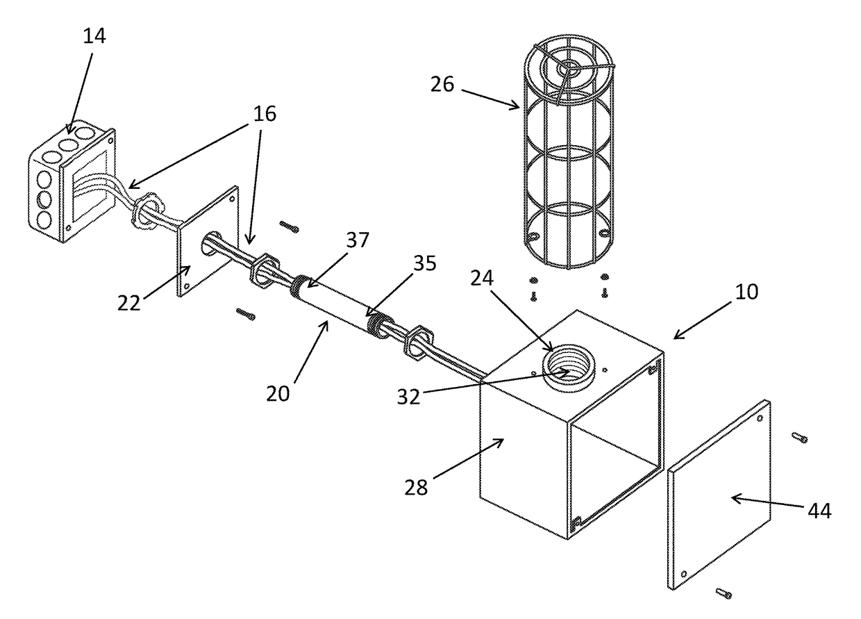
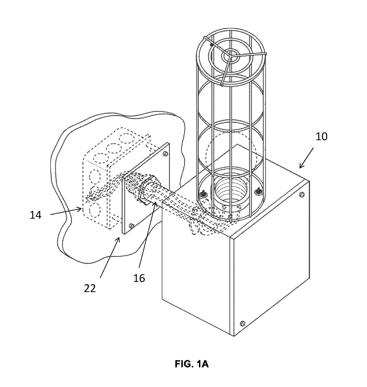
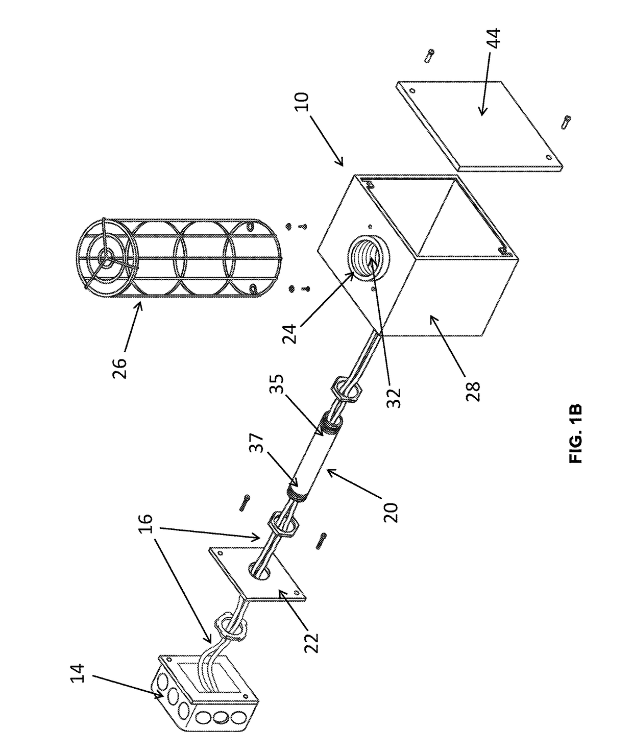
[0025]FIG. 1A is a perspective view of the lighting sconce 10 mounted on a wall. FIG. 1B is a perspective exploded assembly view of the lighting sconce 10 mounted on a wall. In addition to the lighting sconce 10, FIG. 1A displays the lighting sconce 10 as installed on a wall with an in-wall junction box 14 electrical wiring 16.

[0026]As shown in FIGS. 2-3, the lighting sconce 10 primarily comprises a lighting sconce junction box 18, a conduit 20, and a mounting plate 22. Additional embodiments of the lighting sconce 10 may further comprise a light socket 24, and a lightbulb protection sh...


PUM


Abstract

The present invention is a sconce configured to have a removable mounting plate. The removable mounting plate may be removed from the sconce and swapped with a mounting plate of a different size or geometric profile. The installer of the sconce may choose a mounting plate that matches the existing geometric profile of the existing in-wall junction box and thus has the ability to adapt the single sconce to the necessary environment. In another embodiment of the invention, the sconce is configured to have storage space for additional mounting plates for the convenience of the installer. In another aspect of the invention a method for replacing mounting plates and installing the sconce is disclosed.

Description

BACKGROUND OF THE INVENTION[0001]The present invention relates generally to temporary universal lighting sconces used during construction or renovation. More particularly, the present invention relates to a wall sconce system that provides for universal fit across a wide array of junction boxes, covers, and device rings and is reusable across multiple constructions sites.[0002]Wall sconces are electrical lighting fixtures designed to be installed and fixed onto a wall. The light from a sconce typically reflects on the wall and lights up the ceiling and surrounding area. A sconce is typically installed at a height of between about 5 to 7 feet above the floor, or about 1.5 to about 2.14 m above the floor, where it can provide adequate light to the ceiling and where it will not obstruct traffic flow or be collided with by people. In construction sites or in retrofit or remodeling sites, hallways will either be rough framed, or the framing will be either fully or partially covered with ...

Claims


Application Information

Patent Timeline
Patent Type & Authority Applications(United States)
IPC IPC(8): F21S8/00F21V23/00F21V17/10F21V17/12F21V15/01F21V19/00
CPCF21S8/033F21V23/001F21V19/006F21V17/12F21V15/01F21V17/105F21V15/02
Inventor GARVIN, BARTON L.
Owner SOUTHWIRE CO LLC
Why Eureka
Try Eureka