Eureka AIR delivers breakthrough ideas for toughest innovation challenges, trusted by R&D personnel around the world.

Systems and methods for embedded sensors with variance-based logic

Inactive Publication Date: 2018-03-29
WASHINGTON UNIV IN SAINT LOUIS
View PDF6 Cites 0 Cited by
  • Summary
  • Abstract
  • Description
  • Claims
  • Application Information

AI Technical Summary

Benefits of technology

The present invention is a variance-based substrate computing system that uses sensors embedded in structures to generate electrical output signals in response to mechanical input. The processor analyzes these signals to determine variations from a base value and generates a binary output signal based on this variation. This system provides a means of monitoring and measuring mechanical inputs in real-time, providing valuable data for analysis and interpretation.

Problems solved by technology

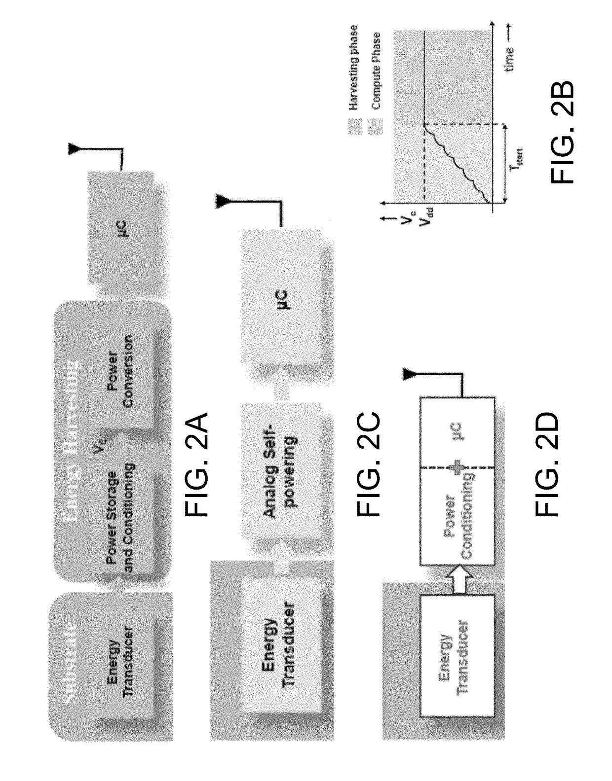
Such power and space constraints may, however, affect the capacity of energy storage or energy harvesting devices be integrated with the sensor.
As a result, a gap may exist between energy that can be scavenged from real-world mechanical structures and the energy density required for performing requisite computing operations.
In addition, although low power sensors have been designed in the past, such sensors often do not generate an output voltage sufficient for the application of standard binary logic operations.
In other words, conventional low power sensors not generate output voltages sufficient to discriminate between a logic high signal and a logic low signal.

Method used


Image

  • Systems and methods for embedded sensors with variance-based logic
  • Systems and methods for embedded sensors with variance-based logic
  • Systems and methods for embedded sensors with variance-based logic

Examples


example 1

Variance-Based Logic and Mean-Based Logic Energy Efficiency

[0095]The energy-efficiency of variance-based logic (VBL) can be compared to the traditional mean-based logic (MBL) by visualizing the process of logic transition, as shown in FIGS. 10C and 10D. For a specific implementation of MBL, the logic transition can be realized by transferring electrons from one potential well to another, as shown in FIG. 10C. The height of the energy barrier E1 which determines the reliability of a logic state is set to be at least E1>KT , where K is the Boltzmann's constant and T is the temperature at which the MBL device is operated. During the logic transition (0 to 1 for example), the energy barrier is lowered and the potential wells are reshaped in a way that the electrons move to the potential well corresponding to logic 1. The energy barrier E1 is then restored and held until the next transition. Assuming irreversible computation and adiabatic transport of the electrons between the potential ...

example 2

Variance-Based Logic and Mean-Based Logic Signal-to-Noise Ratio

[0103]One of methods to approach the fundamental limit of energy-dissipation for MBL is to use error-correcting codes to compensate for high pavg. A more practical approach would be to first boost the signal-to-noise ratio (SNR) of the measurement through repeated sampling and statistical averaging. Given N independent and identically distributed (iid) random samples x1, x2, . . . xN from a distribution with mean μ and variance σ2, the sample mean ({circumflex over (x)}) is defined as:

x^=∑i=1NxiNEquation14

and sample variance is given by:

σ^2=∑i=1N(xi-x^)2N-1.Equation15

The signal-to-noise ratio (SNR) for the measurement is given by:

SNR=E[x^]2E[σ^2].Equation16

In the case of MBL, it is given by:

SNRMBL=Nμ2σ2.Equation17

[0104]Even if the samples are drawn from any given probability distribution the definition of SNRmean holds. Whereas the variance of the sample variance becomes a function of fourth order moment and is estimated...


PUM


Abstract

A variance-based substrate computing system is disclosed. The variance-based computing system includes a sensor configured to be embedded in a structure, the sensor further configured to generate an electrical output signal in response to a mechanical input, and a processor configured to receive the electrical output signal. The processor includes a measurement module configured to determine a variance of the electrical output signal about a base value, and a transformation module configured to generate a binary output signal based upon the variance.

Description

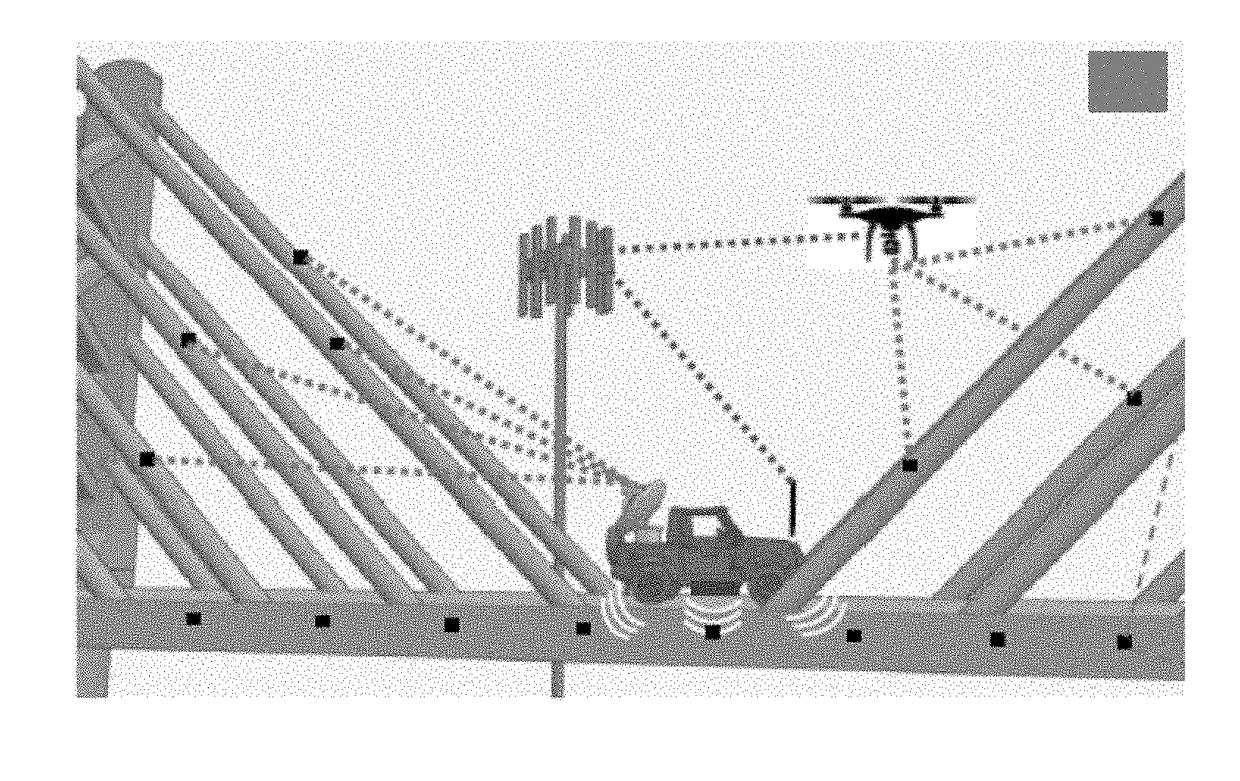
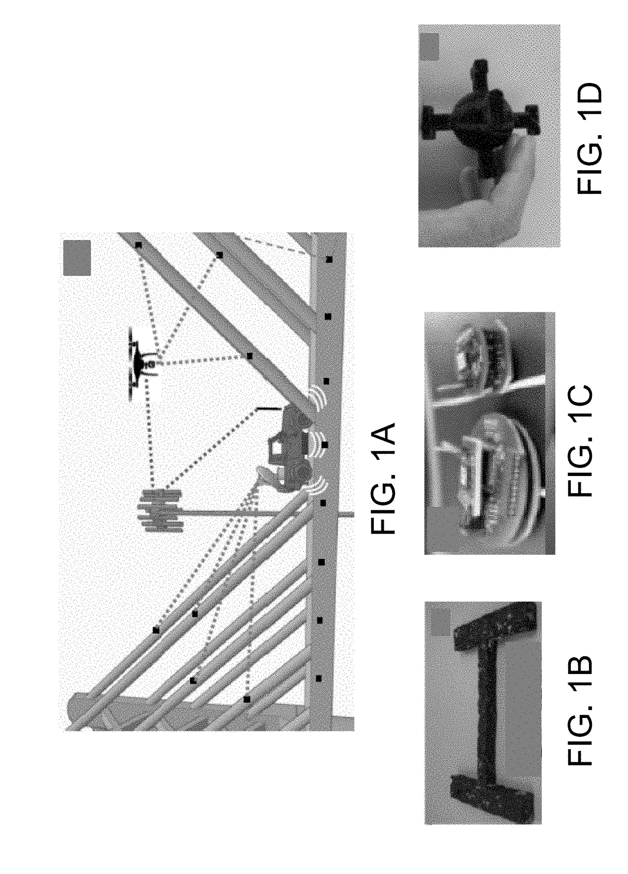
CROSS REFERENCE TO RELATED APPLICATION[0001]This application claims the benefit of U.S. Provisional Patent Application No. 62 / 400,807 filed on Sep. 28, 2016, the contents of which are hereby incorporated by reference for all purposes.STATEMENT REGARDING FEDERALLY SPONSORED RESEARCH & DEVELOPMENT[0002]This invention was made with government support under grants 1405273 and 1550096 awarded by the National Science Foundation. The U.S. government has certain rights in the invention.BACKGROUND[0003]Substrate computing systems include systems, such as sensors, computing or logic components, communication components, energy scavenging and energy storage components, and the like, that are capable of being integrated or embedded within a substrate. A substrate includes a structure or structural component, such as an aircraft wing, a section of a building, a part of a roadway, and the like. Substrate computing systems thus contribute to an infrastructural internet-of-things (i-IoT), in which ...

Claims


Application Information

Patent Timeline
IPC IPC(8): G01H11/06G01M5/00
CPCG01H11/06G01M5/0066H04L67/12
Inventor CHAKRABARTTY, SHANTANUKONDAPALLI, SRI HARSHAZHANG, XUAN
Owner WASHINGTON UNIV IN SAINT LOUIS
Why Eureka
Eureka Blog
Learn More