Systems and methods for providing environmental monitoring and response measures in connection with remote sites

Active Publication Date: 2018-03-29
PILLAR TECH
View PDF9 Cites 24 Cited by
  • Summary
  • Abstract
  • Description
  • Claims
  • Application Information

AI Technical Summary

Benefits of technology

[0011]The system further includes an analytic system and related software platforms for processing and analyzing the sensor information from a plurality of sensors at each of the plurality of base units. The software platforms are configured to perform analytics on data sourced from base units containing the plurality of sensors, databases stored in memory, third-parties, and other source of data relevant to the site or sites being monitored. The system may further include a plurality of external sensor units, sensor arrays, and other peripheral devices which communicate with base units and enhance the functionality of the monitoring and response system. The system may also take action responsive to the information gathered, for example, the system may actuate, deactivat

Problems solved by technology

The use of the measurement methods is sporadic and the repeatability of these measurements cannot be confirmed.
Wireless, stationary unit systems exist to measure specific variables, for example, dust particulate and dangerous gasses; however, these systems are not integrated into a seamless solution for site monito

Method used


Image

  • Systems and methods for providing environmental monitoring and response measures in connection with remote sites
  • Systems and methods for providing environmental monitoring and response measures in connection with remote sites
  • Systems and methods for providing environmental monitoring and response measures in connection with remote sites

Examples


Example

Example 1

[0186]The following is an example of the monitoring system operating in accordance with a preferred embodiment of the present disclosure.

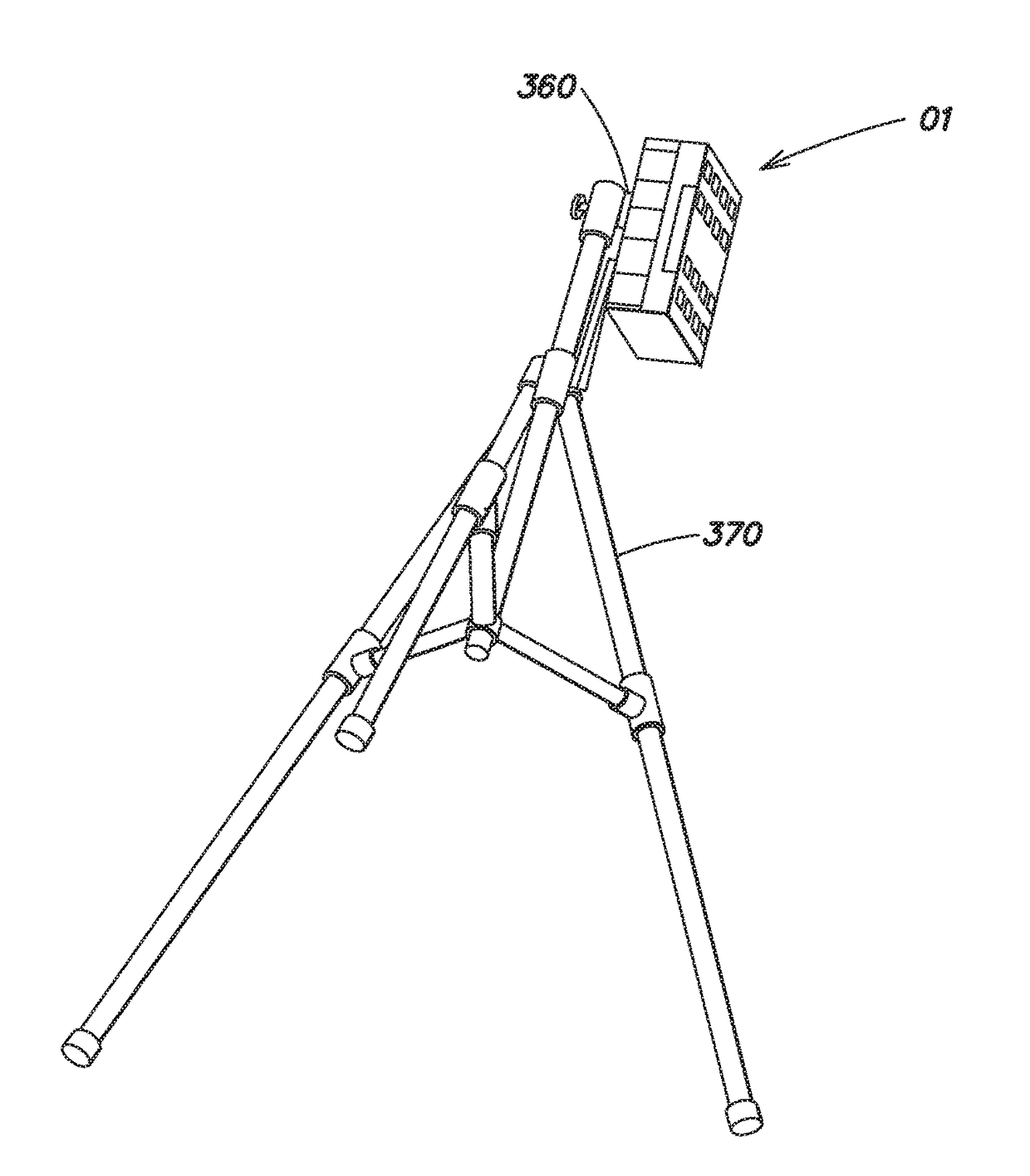
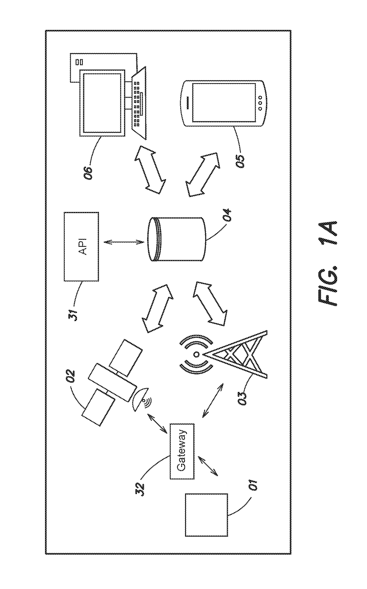
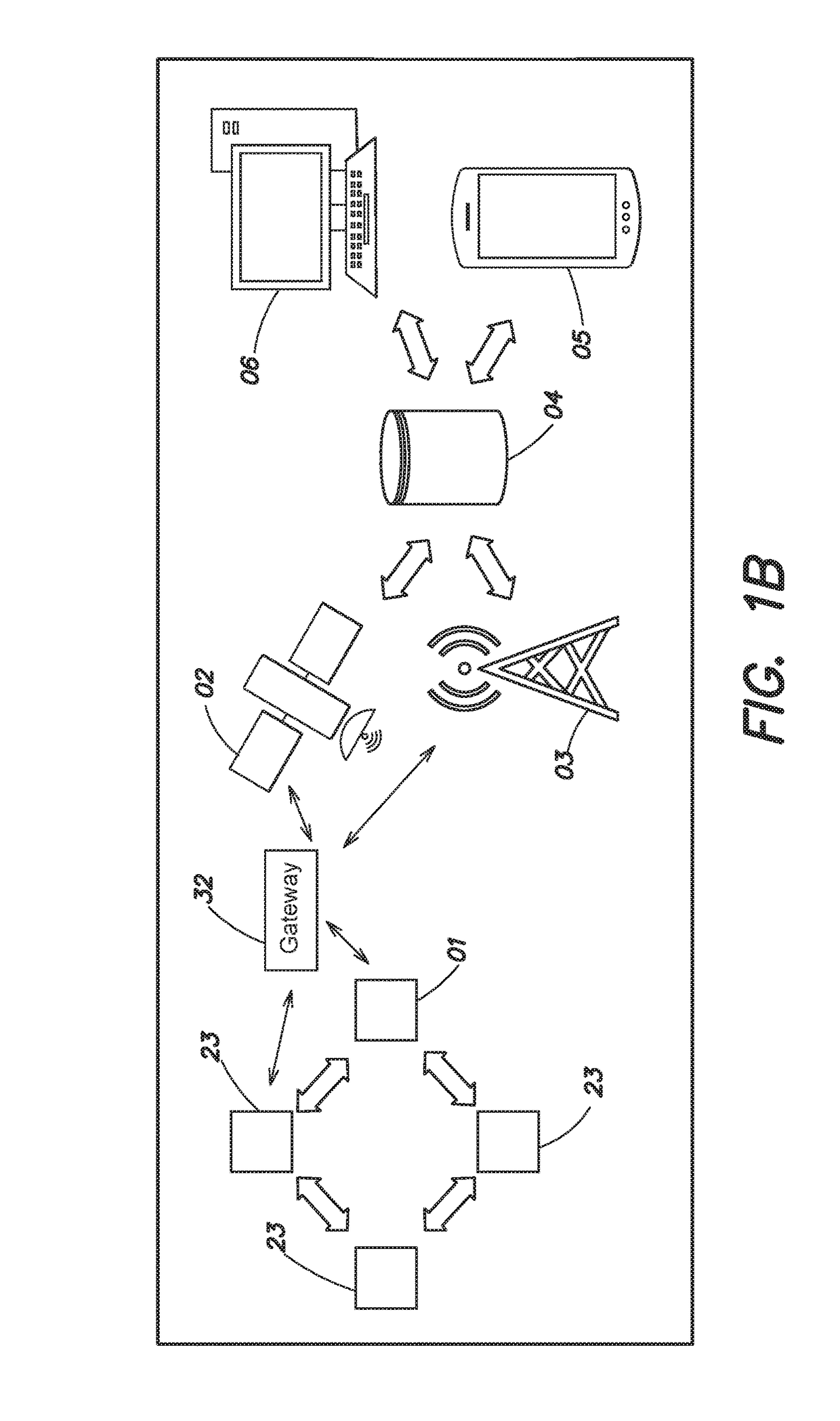
[0187]A construction site consisting of a basement and several above-ground floors is outfitted with a plurality of base units 01. A number of areas within the site contain magnetically-active metal structures and, in those areas, base units 01 are removably affixed to the structures using magnet mounts 360. In other areas, base units 01 are removable affixed to 2 x 4 pieces of wood via mounting straps 1371. A wireless networking gateway 32 is disposed near the spatial center of the site and allows the base units to wirelessly connect via LPWAN to the gateway 32 and provides access to a cellular data connection over 3G or 4G. The server 04 is hosted on the Internet and may be accessed using the cellular data connection.

[0188]The controller 18 in each base unit 01 executes a series of instructions corresponding to the method of networking c...

Example

Example 2

[0193]The following is an example of the monitoring system operating in accordance with a preferred embodiment of the present disclosure.

[0194]A construction project within or adjacent to an active hospital consisting of an area where there is access for entry or exit between the construction project and the active hospital is outfitted with a plurality of base units 01. Base units 01 are removably affixed to both sides of the entryway with one base unit 01 removably affixed within the active hospital side of the entryway and another base unit 01 removably affixed within the construction project side of the entryway. Base units 01 may be removably affixed at the same height from the floor to ensure accurate barometric pressure readings. A wireless networking gateway 32 is disposed near the spatial center of the site and allows the base units to wirelessly connect via LPWAN to the gateway 32 and provides access to a cellular data connection over 3G or 4G. The server 04 is ho...


PUM


Abstract

A monitoring and response system is provided for monitoring and responding to environmental conditions at one or more sites. The monitoring system includes a plurality of base units, each base unit including at least a processor and a plurality of sensors configured to monitor environmental conditions at the site(s). A central controller is in communication with the base processors at the plurality of base units and is configured to receive and process sensor information from the base units. Base units are configured to be modular and contain customizable, swappable combinations of sensors, sensor arrays, and/or other connected peripherals, and are further configured to be mountable and/or attachable to a wide variety of surfaces and objects disposed around a site such as a construction site. The system further comprises a backend, analytic system for making predictions, taking action, and generating reports responsive to the information received from the base units.

Description

CROSS-REFERENCE TO RELATED APPLICATION[0001]This application claims priority under 35 U.S.C. § 120 as a continuation-in-part of U.S. patent application Ser. No. 15 / 349,811 titled “SYSTEMS AND METHODS FOR PROVIDING ENVIRONMENTAL MONITORING AND RESPONSE MEASURES IN CONNECTION WITH REMOTE SITES,” filed Nov. 11, 2016 which claims priority under 35 U.S.C. § 119(e) to U.S. Provisional Application Ser. No. 62 / 268,260 titled “SYSTEMS AND METHODS FOR PROVIDING RISK MANAGEMENT, MONITORING AND ALARM SYSTEMS IN CONNECTION WITH REMOTE SITES,” filed Dec. 16, 2015. This application also claims priority 35 U.S.C. § 119(e) to U.S. Provisional Application Ser. No. 62 / 420,984, titled “SYSTEMS AND METHODS FOR PROVIDING ENVIRONMENTAL MONITORING AND RESPONSE MEASURES IN CONNECTION WITH REMOTE SITES,” filed Nov. 11, 2016 and to U.S. Provisional Application Ser. No. 62 / 468,136, titled “SYSTEMS AND METHODS FOR PROVIDING ENVIRONMENTAL MONITORING AND RESPONSE MEASURES IN CONNECTION WITH REMOTE SITES,” filed M...

Claims


Application Information

Patent Timeline
IPC IPC(8): G08B25/10H04Q9/02G06Q10/06G06Q30/00G06Q50/08
CPCG08B25/10H04Q9/02G06Q10/0635G06Q30/018G06Q50/08H04Q2209/10H04Q2209/40H04Q2209/826H04Q2209/84H04Q2209/88G08B29/185H04Q9/00
Inventor SCHWARZKOPF, ALEXANDER MESSERSMITHJOYAL, MATTHEW JEAN-MARIE JOSEPHIACOBONE, SEAN PETER
Owner PILLAR TECH
Why Eureka
Try Eureka