Base station, user equipment, and method for determining precoding matrix

a precoding matrix and base station technology, applied in the field of physical and link layer designs of wireless systems, can solve the problems of lowering the accuracy of channel information obtained based on channel reciprocity, unable to adapt to link adaptation solely on channel reciprocity, and unable to use part or all of channel information, etc., to achieve high accuracy channel state estimation and effective precoding processing

Inactive Publication Date: 2018-03-29
NTT DOCOMO INC
View PDF3 Cites 37 Cited by
  • Summary
  • Abstract
  • Description
  • Claims
  • Application Information

AI Technical Summary

Benefits of technology

[0018]According to another aspect of the present invention, a wireless communication system may comprise the base station and user equipment as described above. The base station, the user equipment, and the method for determining the precoding matrix according to one or more embodiments of the present invention enable highly accurate channel state estimation and effective precoding processing in 3D MIMO.

Problems solved by technology

If accuracy of calibration is low, accuracy of channel information obtained based on channel reciprocity is lowered, and as a result, a part or all of the channel information may be unusable.
However, link adaptation depending solely on channel reciprocity may not be possible due to RF imperfections and reception quality of reference signals.
Furthermore, link adaptation depending on channel reciprocity only may have limitations in some situations even if RF imperfections do not cause problems and reception quality is sufficiently high.
However, it may be difficult to control the number of multiple layers and the encoded modulation system because the base station cannot estimate channel quality and interference conditions in the user equipment.
In addition, as described above, if the number of antennas of uplink and the number of antennas of downlink are asymmetrical, channel state information obtained by channel reciprocity is limited.
In addition, in a case where channel reciprocity is used, it may be difficult to perform adaptive control of the number of multiple layers and the encoded modulation system because the base station cannot estimate received power and interference conditions in the user equipment.

Method used


Image

  • Base station, user equipment, and method for determining precoding matrix
  • Base station, user equipment, and method for determining precoding matrix
  • Base station, user equipment, and method for determining precoding matrix

Examples


Embodiment Construction

[0031]Embodiments of the present invention will be described below with reference to the drawings.

(System Configuration)

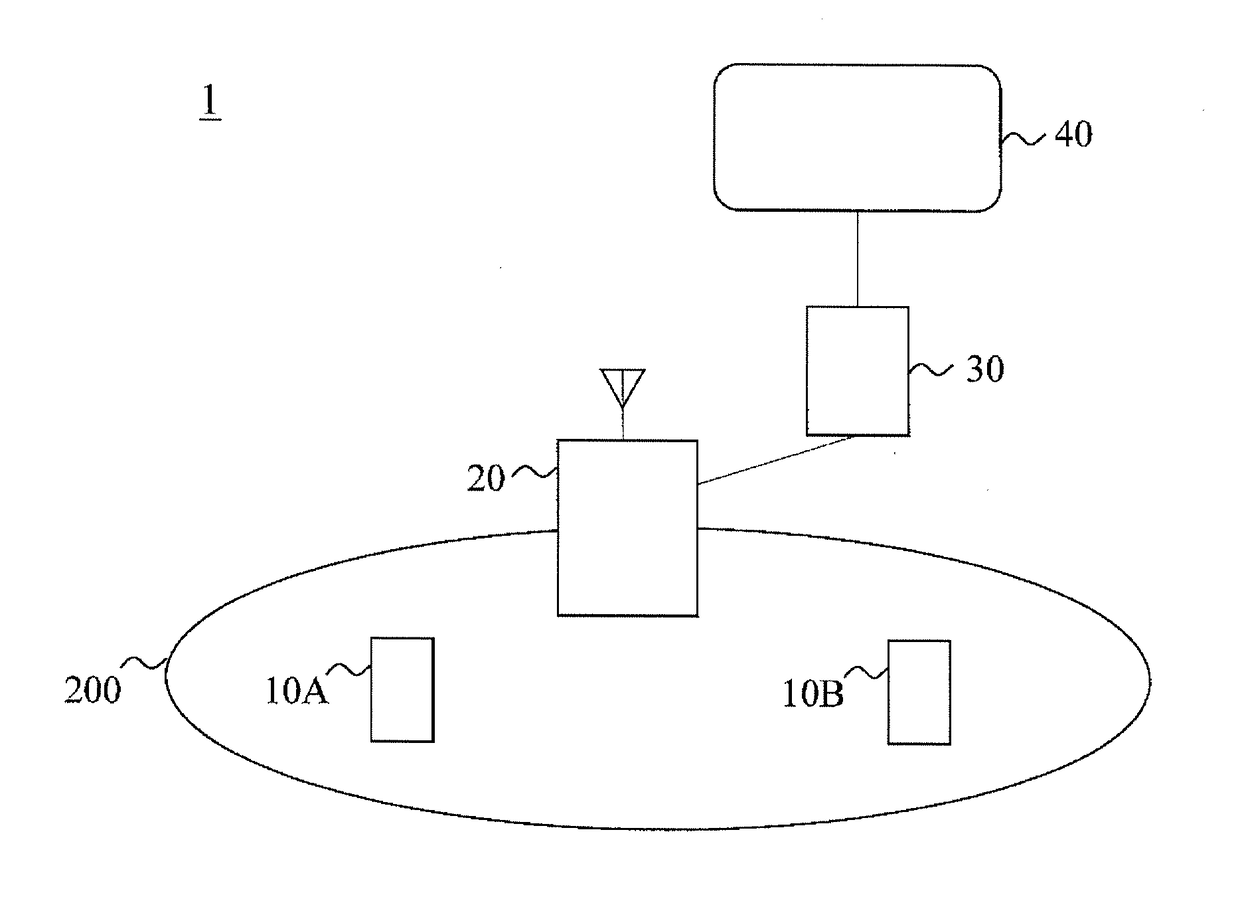
[0032]A wireless communication system 1 according to one or more embodiments of the present invention will be described below with reference to FIG. 3. FIG. 3 is a diagram showing a configuration of the wireless communication system 1 according to one or more embodiments of the present invention.

[0033]As shown in FIG. 3, the wireless communication system 1 comprises a user equipment (UE) 10 (UE 10A and UE 10B), a base station 20 including a cell 200, an access gateway apparatus 30, and core network 40. The wireless communication system 1 is a 3D MIMO system and may be an LTE system or an LTE-Advanced (LTE-A) system. However, the wireless communication system 1 is not limited thereto and may be any one of a wireless communication system supporting 3D MIMO communication. 3D MIMO may be classified as Elevation beamforming (BF) and Full dimension (FD)-MIMO according to...


PUM


Abstract

A base station that communicates with a user equipment using multiple antenna ports includes an uplink channel estimation unit that estimates uplink channel states, a downlink channel estimation unit that estimates downlink channel states based on the estimated uplink channel states and channel reciprocity of uplink and downlink, a receiver unit that receives from the user equipment CSI feedback information, and a precoder generating unit that determines a precoding matrix of downlink based on Channel State Information (CSI) indicating the estimated downlink channel states and on the CSI feedback information.

Description

TECHNICAL FIELD[0001]The present invention relates generally to physical and link layer designs of wireless systems such as LTE (Long Term Evolution). The design uses complemental feedback of channel state information for multi-antenna transmission system exploiting channel reciprocity.BACKGROUND ART[0002]Advancements in MIMO (Multiple Input Multiple Output) technologies using multiple transmitter and receiver antennas are being studied under the LTE standard. For example, in typical downlink MIMO communication, a user equipment (UE) estimates downlink channel states based on downlink reference signals from the base station. The UE reports the estimated downlink channel states as channel state information (CST) feedback information to the base station. The base station then performs link adaptation for downlink data transmission based on the CSI feedback information. Typical link adaptation may include control of the number of spatial multiplexing layers, transmission beam control, ...

Claims


Application Information

Patent Timeline
Patent Type & Authority Applications(United States)
IPC IPC(8): H04B7/06H04B7/04H04L25/03
CPCH04B7/0626H04B7/0639H04B7/0469H04L25/03343H04B7/0632H04L25/03891H04B7/0413H04B7/0479
Inventor KAKISHIMA, YUICHINAGATA, SATOSHINA, CHONGNINGHOU, XIAOLINJIANG, HUILING
Owner NTT DOCOMO INC
Why Eureka
Try Eureka