
Light emitting diode (LED) lighting device or lamp with configurable light qualities

a technology of light-emitting diodes and lighting devices, which is applied in the direction of fixed installation, lighting and heating equipment, light source combinations, etc., can solve the problems of compact fluorescent bulbs that are reduce the aesthetic appeal of compact fluorescent bulbs, and the color temperature of light emitted by compact fluorescents is not aesthetically pleasing for many applications

Active Publication Date: 2018-03-29
FEIT ELECTRIC CO INC
View PDF4 Cites 18 Cited by
  • Summary
  • Abstract
  • Description
  • Claims
  • Application Information

AI Technical Summary

Benefits of technology

The present invention provides an LED lighting device or LED lamp with configurable aspects such as color temperature, brightness, and color rendering index (CRI). The LED lamp or LED lighting device allows users to select an operating mode and control the light emitted through a user-selection switch. The device can be controlled through a remote switch or a portable device. The technical effect of this invention is that users can adjust the light emitted from the LED lamp or LED lighting device to their preferences and needs, making it more flexible and customizable.

Problems solved by technology

Additionally, many people find the color temperature of light emitted by compact fluorescents to not be aesthetically pleasing for many applications, such as household lighting in kitchens, bathrooms, and living rooms; some commercial applications; and the like.
Due to the nature of compact fluorescent bulbs, the bulbs always have a frosted appearance, which also tends to reduce the aesthetic appeal of compact fluorescent bulbs.
The use of halogen bulbs has also increased; however due to the high temperatures at which halogen bulbs operate they are not highly efficient and may be a fire or burn hazard.

Method used


Image

  • Light emitting diode (LED) lighting device or lamp with configurable light qualities
  • Light emitting diode (LED) lighting device or lamp with configurable light qualities
  • Light emitting diode (LED) lighting device or lamp with configurable light qualities

Examples


example driver

Circuitry

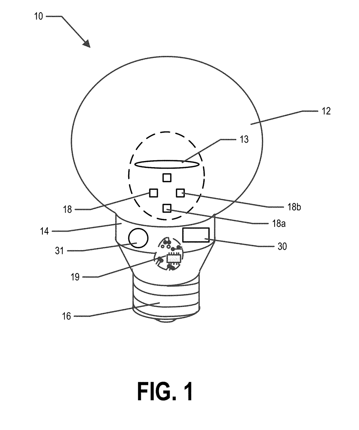
[0042]In example embodiments, the driver circuitry 19 may be configured to provide a controlled electrical current to at least one of the LED packages 18 during operation of the LED lighting device 20 or LED lamp 10. In various embodiments, the driver circuitry 19 may comprise a circuit portion configured to convert AC voltage into DC voltage. In some embodiments, the driver circuitry 19 may comprise a circuit portion configured to control the current flowing through the two or more LED packages 18. In certain embodiments, the driver circuitry 19 may comprise a circuit portion configured to dim the LED lamp 10 or LED lighting fixture 20. In various embodiments, additional circuit components may be present in the driver circuitry 19. Similarly, in various embodiments, all or some of the circuit portions mentioned here may not be present in the driver circuitry 19. In some embodiments, circuit portions listed herein as separate circuit portions may be combined into one circui...

example switch

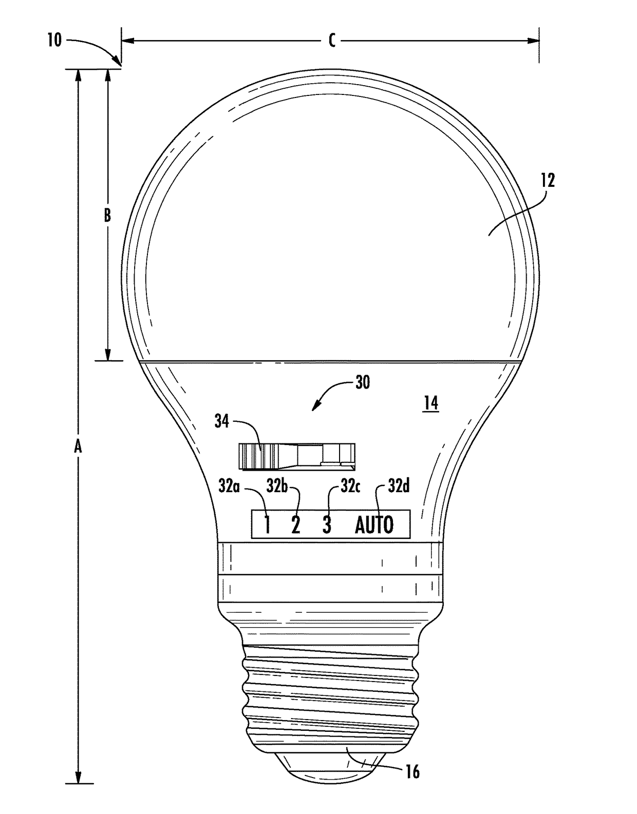
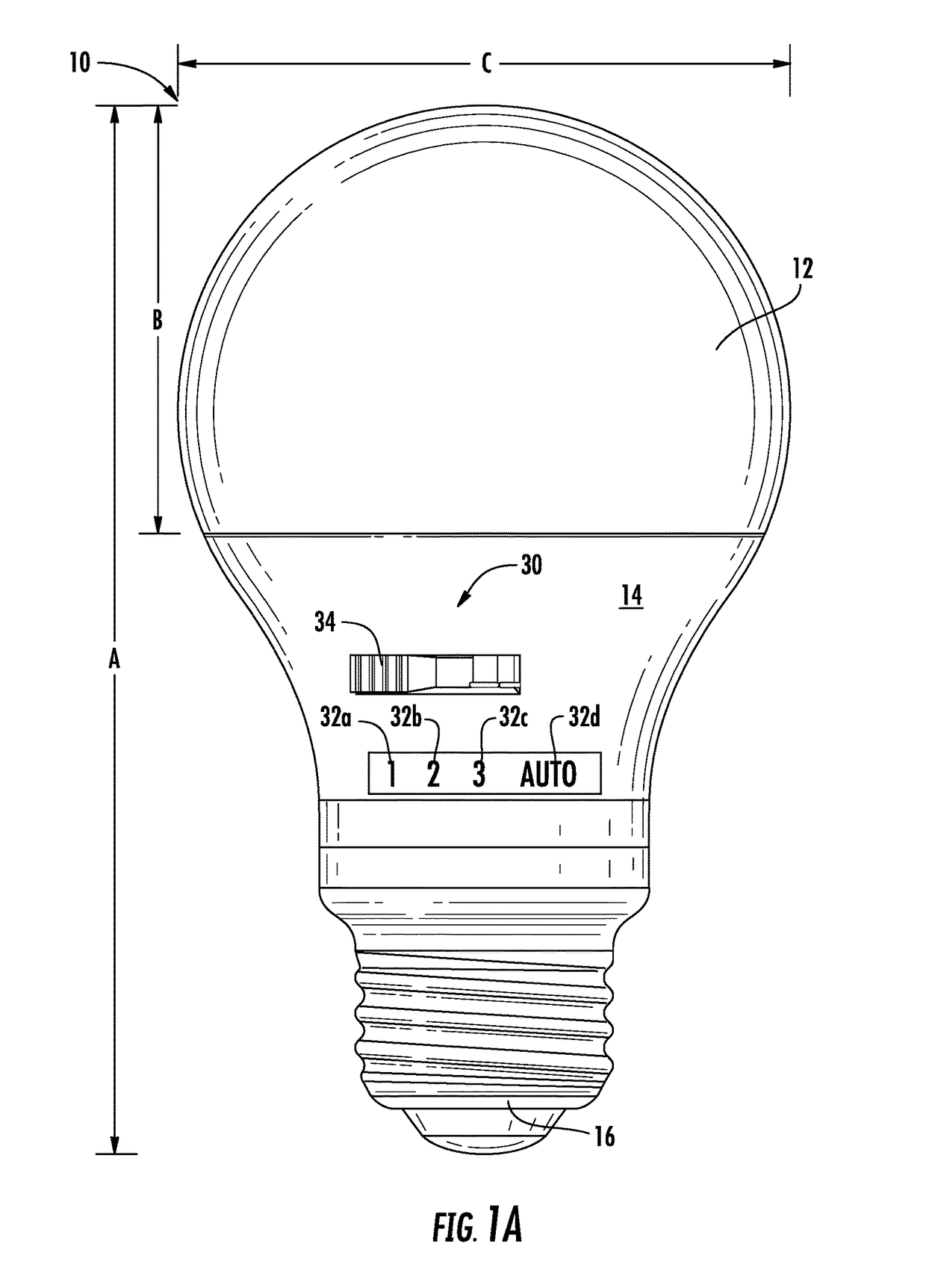
[0049]In example embodiments, the LED lamp 10 and / or LED lighting device 20 comprises a switch 30. In example embodiments, the switch 30 may be configured to allow a user to select an operating mode (e.g., a programmable custom mode, a set mode, or a configurable mode). One or more aspects or qualities of the light (e.g., color temperature, brightness, CRI, and / or the like) emitted by the LED lamp 10 and / or LED lighting device 20 may then be controlled based on the user-selected operating mode. In example embodiments, the switch 30 may be a mechanical switch, electro-mechanical switch, an infrared switch, and / or the like. For example, if the switch 30 is a mechanical switch, the switch 30 may comprise a slide switch, a dial, a set of binary switches, and / or the like. In an example embodiments, the switch 30, and / or a user interface thereof, may be disposed on an exterior surface of the lamp housing 14 or the device housing 24. FIGS. 3 and 3A provide block diagrams of at least some o...

example remote

Switch

[0061]Example embodiments of the present invention comprise a remote switch 40. In example embodiments, a remote switch 40 may be a wall mounted switch mounted in the same room as the LED lamp 10 or LED lighting device 20 and / or within a short range communication technology range of the LED lamp 10 or LED lighting device 20. For example, the remote switch 40 may be a wall and / or junction box mounted toggle switch, dimmer switch and / or the like in wired communication with the switch control unit 35. In another example, the remote switch 40 may be a handheld device (e.g., a remote control, or computing entity 40′) that is within the same room as the LED lamp 10 or LED lighting device 20, within a short range communication technology range of the LED lamp 10 or LED lighting device 20, in communication with the switch control unit 35 through a wireless network, and / or the like. In example embodiments, the remote switch 40 may be in wired or wireless communication with the switch c...


PUM


Abstract

An LED lighting device or LED lamp comprises one or more LED packages, and a switch comprising at least two selectable positions. At least one selectable position corresponds to a set operating mode and one selectable position corresponds to a configurable operating mode. When the switch is in the selectable position corresponding to the set operating mode, responsive to receiving an indication of user input for selecting user-selected operating light qualities, the one or more LED packages continue to be operated in accordance with the predefined operating light qualities corresponding to the set operating mode. When the switch is in the selectable position corresponding to the configurable operating mode, responsive to receiving an indication of user input for selecting user-selected operating light qualities, operation of the one or more LED packages is modified in accordance with the user-selected operating light qualities.

Description

CROSS-REFERENCE TO RELATED APPLICATIONS[0001]This application is a continuation of U.S. application Ser. No. 15 / 274,575, filed Sep. 23, 2016, the contents of which are incorporated by reference herein in their entireties.BACKGROUND[0002]Incandescent bulbs are slowly being phased out in favor of more efficient lighting sources. This has led to an increased use of compact fluorescent bulbs which are more efficient than incandescent bulbs, but which tend to contain dangerous gasses, such as mercury. Compact fluorescent bulbs are also affected by ambient temperature and fail reach their peak brightness in colder conditions. Additionally, many people find the color temperature of light emitted by compact fluorescents to not be aesthetically pleasing for many applications, such as household lighting in kitchens, bathrooms, and living rooms; some commercial applications; and the like. Due to the nature of compact fluorescent bulbs, the bulbs always have a frosted appearance, which also ten...

Claims


Application Information

Patent Timeline
Patent Type & Authority Applications(United States)
IPC IPC(8): H05B33/08H05B37/02F21V23/04F21V23/00F21V19/00F21V3/00H05B44/00
CPCF21V3/00F21Y2115/10F21K9/235F21V19/006F21V23/04F21K9/65H05B37/0272F21V23/003F21K9/237F21K9/238H05B33/0857H05B33/0845F21K9/232F21V29/70H05B39/088F21S8/02F21Y2113/13H05B45/20H05B47/19Y02B20/30H05B47/1965
Inventor HALLIWELL, BRIAN
Owner FEIT ELECTRIC CO INC
Learn More