Eureka AIR delivers breakthrough ideas for toughest innovation challenges, trusted by R&D personnel around the world.

Headgear for dry electroencephalogram sensors

Active Publication Date: 2018-04-05
COGNIONICS
View PDF9 Cites 29 Cited by
  • Summary
  • Abstract
  • Description
  • Claims
  • Application Information

AI Technical Summary

Benefits of technology

The invention is a new kind of dry EEG headgear that solves problems with previous headgear designs. It has very few parts and can be easily adjusted to fit different head sizes and shapes. It also has sensors placed on the upper part of the head, which can help gather important information. Overall, this headgear is easy to wear and can help make EEG measurements quick and easy.

Problems solved by technology

In many cases, abrasion of the scalp is necessary.
However, the use of electrolytic gels, adhesives and scalp abrasion is often time consuming, irritating and uncomfortable for the subject.
In practice, dry electrodes suffer from numerous usability issues.
However, elastic caps suffer from a numerous problems.
Although elastic caps are generally flexible, the generic ‘balloon-like’ shape does not fully conform well to the exact contours of different head shapes (e.g., ‘boxy’ heads or dimples), leading to areas where the cap is overly tight and other areas where the cap is loose.
In addition, the closed nature of the cap makes adjusting the electrodes difficult in cases where the electrodes are in the wrong position or poorly contacting the scalp.
Finally, because the elastic cap has no rigid supports, individual electrodes inside the cap are prone to tipping and misalignment during application.
This system is effective at providing optimized and individual tension for each of the sensors in the array but the overall design is complex and bulky.
Each headgear contains multiple joints, springs and other moving parts making the system heavy and expensive.
However, the design shown by Trewartha imposes severe geometric constraints, especially for EEG applications which involve placement of the sensors at specific locations around the scalp.
While this is effective in securing the headgear to the user, the arrangement biases the locations of the electrodes to the sides of the head—areas that are particularly prone to muscular artifacts.
Placement of sensors on the upper half of the head and the back of the head, which is necessary for many research and medical EEG applications, cannot be readily accommodated with this setup.

Method used


Image

  • Headgear for dry electroencephalogram sensors
  • Headgear for dry electroencephalogram sensors
  • Headgear for dry electroencephalogram sensors

Examples


Embodiment Construction

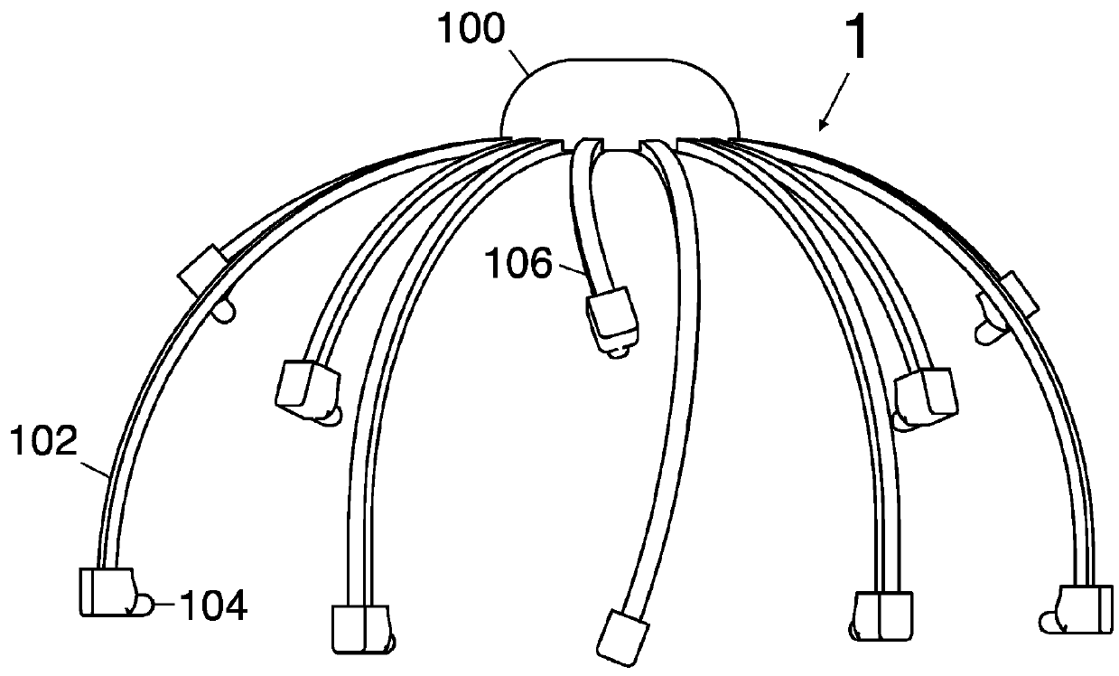
[0024]Referring to FIG. 1, an exemplary embodiment of a headgear 1 according to the invention includes a centerpiece 100, lower arms 102, sensor tips 104 and an upper arms 106. A preferred embodiment of the headgear 1 contains at least two lower arms 102 and optionally one or more upper arms 106. However, for purposes of clarity, the descriptions below will refer to each generically rather than as specific individual units since embodiments may have multiple, similar copies of each.

[0025]The centerpiece 100 provides a reference position for the entire headgear 1. In the exemplary embodiment shown in FIG. 1, the centerpiece 100 is a dome with sufficient interior volume to house the electronics for the headgear 1. The centerpiece is an ideal location for placing electronic components for sensing neurological signals, such as amplifiers, microprocessors, wireless transceivers and control buttons since it is equidistant from all peripheral sensor points and facilitates easy access by th...


PUM


Abstract

A headgear for placing sensors on a subject's head includes a centerpiece; a plurality of arms attached to and radiating outward and generally downward from the centerpiece; and sensor tips attached to the dorsal ends of at least some of the arms. At least one of the plurality of arms is a lower arm that is elastic and / or spring-like. When the headgear is placed on a subject's head, the at least one lower arm is so disposed in relation to the maximum circumference of the subject's head that the at least one lower arm must be bent outward for placement of the headgear on the subject's head and thereby provide a reactive force toward the head that causes the at least one lower arm to grasp at least a portion of the head that is at and / or below the maximum circumference of the head.

Description

CROSS REFERENCE TO RELATED APPLICATIONS[0001]This application is a continuation-in-part of U.S. patent application Ser. No. 15 / 300,992 filed Sep. 30, 2016.BACKGROUND OF THE INVENTION[0002]The invention relates to headgears and mounting apparatuses, specifically devices that enable the rapid and reliable placement of sensors on a subject's head. The focus of this patent is for dry electrode EEG applications, although the invention is broadly applicable to placing any type sensor or transducer on the head of a subject.[0003]Conventional recording of EEG signals predominantly involves the use of wet electrodes that utilize a gel for conduction to the subject's scalp. The wet electrodes can be affixed to the skin either with glue or placed in an elastic cap. In many cases, abrasion of the scalp is necessary. The high conductivity of the gel allows electrical conductivity to permeate through hair and any physical gaps between the surface of the electrode and the surface of the scalp is f...

Claims


Application Information

Patent Timeline
IPC IPC(8): A61B5/00A61B5/0478A42B1/24
CPCA61B5/6803A61B5/0478A61B2562/04A61B2562/0209A42B1/242A61B5/7225A61B5/291
Inventor KERTH, TREVOR AUSTINCHI, YU MIKETRAN, AILEEN NGOC
Owner COGNIONICS
Why Eureka
Eureka Blog
Learn More