Backplate molding devices and methods for curved displays

a technology of backplate molding and curved displays, applied in the field of display technology, can solve the problems of low yield rate, achieve the effects of reducing the demands of the punching machine, strengthening the backplate, and reducing the single-time punching dimension

Inactive Publication Date: 2018-04-05
TCL CHINA STAR OPTOELECTRONICS TECH CO LTD
View PDF9 Cites 2 Cited by
  • Summary
  • Abstract
  • Description
  • Claims
  • Application Information

AI Technical Summary

Benefits of technology

[0021]In view of the above, as the plastic deformation and hardening processes are applied to the backplate, the strength of the backplate ensured while the backplate is thin. Also, the curved surface of the backplate is precise. In addition, the punching heads may independently conduct the punching process to greatly reduce the single-time punching dimension, which reduces the demands toward the punching machine of high tonnage. Further, the flow of the workpieces may be easily controlled, and the workpieces are prevented from being damaged for the reason that the workpiece may be uniformly stretched. The curvature of each of the punching heads may be controlled to realize the degree of the arc of each of the punching heads, which contributes to the adjustment of the workpiece and the molding device.

Problems solved by technology

In addition, as the workpiece is thinner, the workpiece may be damaged due to non-uniform stretch, which results in a low yield rate.

Method used


Image

  • Backplate molding devices and methods for curved displays
  • Backplate molding devices and methods for curved displays
  • Backplate molding devices and methods for curved displays

Examples


Embodiment Construction

[0027]Embodiments of the present invention are described in detail with the technical matters, structural features, achieved objects, and effects with reference to the accompanying drawings as follows. It is clear that the described embodiments are part of embodiments of the present invention, but not all embodiments. Based on the embodiments of the present invention, all other embodiments to those of ordinary skill in the premise of no creative efforts obtained, should be considered within the scope of protection of the present invention.

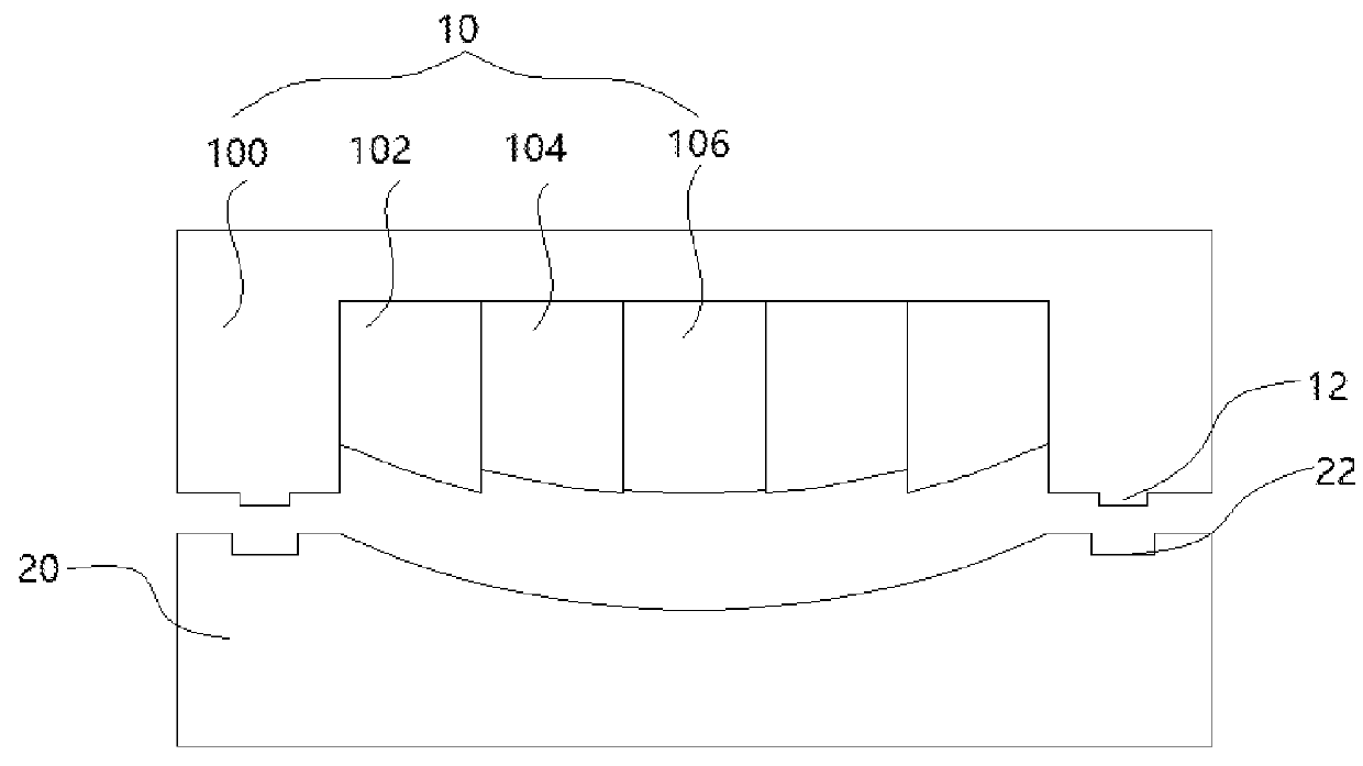
[0028]FIG. 1 is a schematic view of the backplate molding device of curved displays in accordance with a first embodiment. As shown, the device includes a top mold 10 and a down mold 20. The top mold 10 includes a third punching head 106, two second punching heads 104, and two first punching heads 102 arranged along a direction from a middle portion to two lateral sides, and a pressure plate 100. A slider structure is respectively arranged between ...


PUM

PropertyMeasurementUnit
yield rateaaaaaaaaaa
strengthaaaaaaaaaa
curvatureaaaaaaaaaa

Abstract

A backplate molding device includes a top mold and a down mode. The top mold includes a plurality of punching heads having curved operation surfaces and a pressure plate. The punching heads are arranged in multi-sections and the pressure plate is arranged at a lateral side of the punching heads in the multi-section. An operation surface of the down mold is a curved surface engageable with the operation surfaces of the punching heads in the multi-section, and edges of the down mold cooperatively engages with the pressure plate to fix backplate materials. A punching process is applied toward the backplate material by bonding the operation surface of the punching heads with the operation surface of the down mold in sequence to plastically deform the backplate materials. The present disclosure also relates to a backplate molding method.

Description

CROSS REFERENCE[0001]This application claims the priority of Chinese Patent Application No. 201610246438.8, entitled “Backplate molding devices and methods for curved displays”, filed on Apr. 20, 2016, the disclosure of which is incorporated herein by reference in its entirety.FIELD OF THE INVENTION[0002]The present invention relates to a display technology field, and more particularly to a backplate molding device and a plate molding method for curved displays.BACKGROUND OF THE INVENTION[0003]With the development of display technology, super thin design has been a trend of curved displays. Usually, the curved display includes a backplate, a backlight unit, and a display panel. The backlight unit and the display panel are fixed on the backplate in a predetermined curved state so as to be the same curved as the backplate. Thus, it is important to design and manufacture the backplate to be as light and thin as possible while the curved state is maintained.[0004]Currently, the backplat...

Claims


Application Information

Patent Timeline
Patent Type & Authority Applications(United States)
IPC IPC(8): B21D22/06B21D37/10B21D37/08
CPCB21D22/06B21D37/10B21D37/08B29L2031/3475B21D24/16
Inventor HSIAO, YUCHUNLI, DEHUAYU, GANGQUE, CHENGWEN
Owner TCL CHINA STAR OPTOELECTRONICS TECH CO LTD
Why Eureka
Try Eureka