
Vaporizer

a technology of vaporizer and inhalation chamber, which is applied in the field of vaporizers, can solve the problems of not allowing the user to obtain a “fresh” inhalation and providing a and achieves the effect of less enjoyable experience for the user

Active Publication Date: 2018-04-12
ZIPLINE INNOVATIONS LLC
View PDF0 Cites 66 Cited by
  • Summary
  • Abstract
  • Description
  • Claims
  • Application Information

AI Technical Summary

Benefits of technology

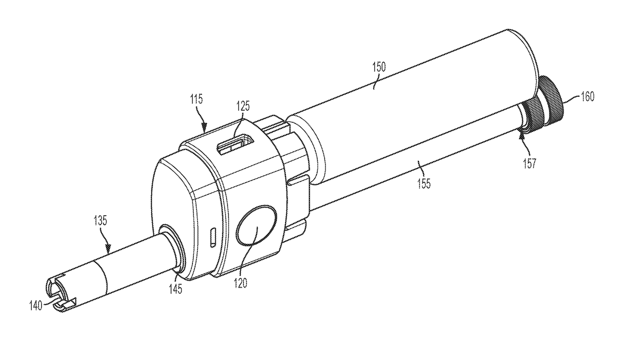
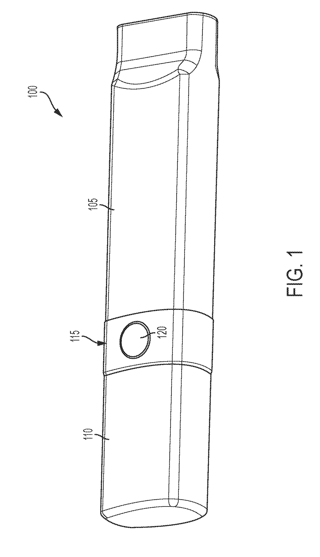
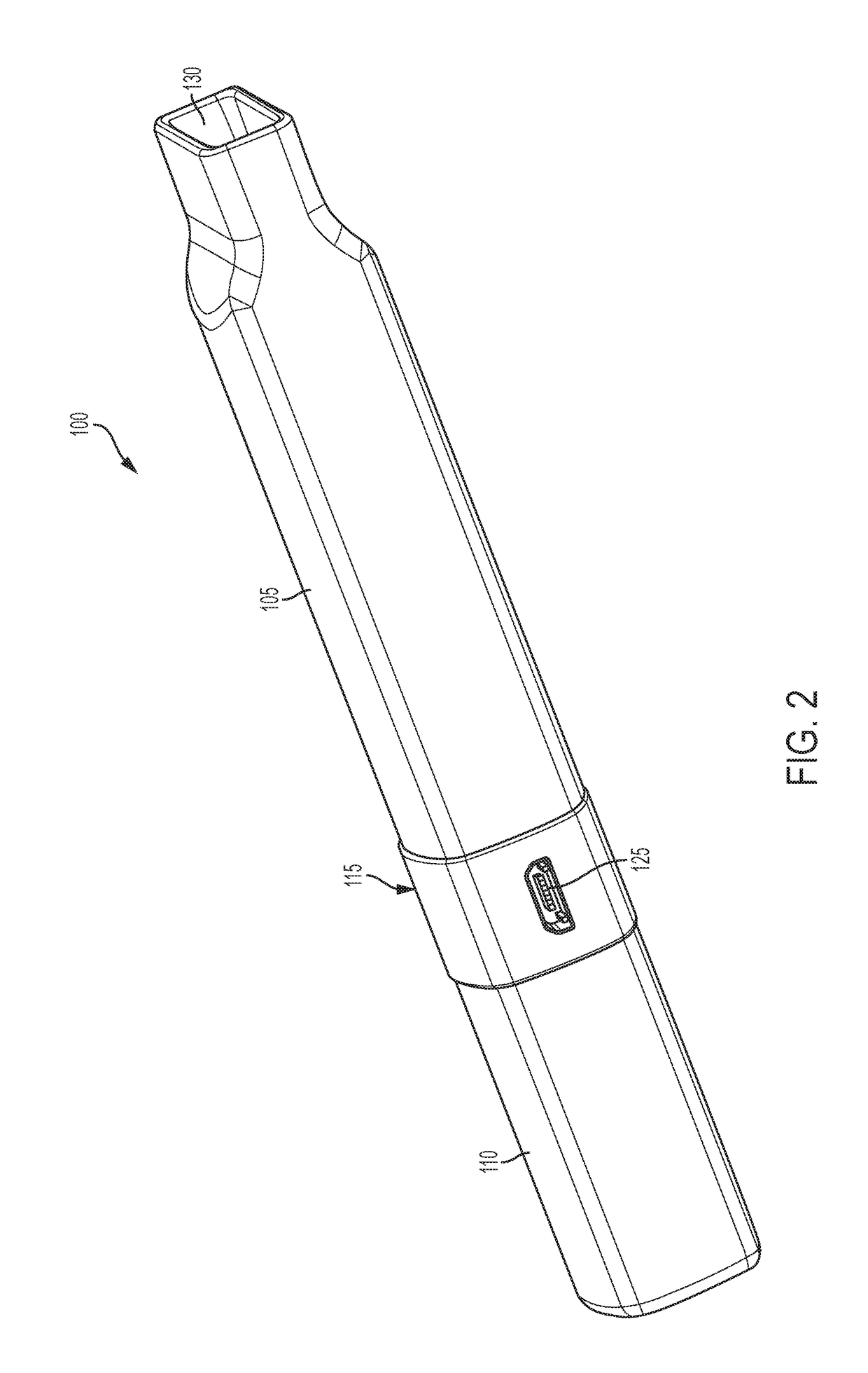
The present patent embodiments are for a vaporizer with a heating element located at one end and a mouthpiece at the other. The heating element can contact the product outside the vaporizer instead of requiring a separate loading canister, which reduces the burnt taste. The heating element can be designed in a straw-like shape to improve air flow during inhalation. The vaporizer is easy to clean and replace parts, and can be removed from the rest of the device for travel with the user. The vaporizer can also include a removable air flow tip and tube, providing more flexibility in cleaning and replacement. The mouthpiece includes a button that activates the heating element, causing it to get hotter. Overall, the patent provides a more convenient and efficient vaporizer for users.

Problems solved by technology

Conventional vaporizers are effective at vaporizing herbal products, but do not allow the user to obtain a “fresh” inhalation other than the first time the product is heated.
Subsequent heatings of the product may therefore taste burnt or otherwise lack the clean flavor of the first inhalation, providing a less enjoyable experience for the user.

Method used


Image

  • Vaporizer
  • Vaporizer
  • Vaporizer

Examples


Embodiment Construction

[0015]While this invention is susceptible of embodiments in many different forms, there is shown in the drawings, and will herein be described in detail, embodiments of the invention with the understanding that the present disclosure is to be considered as an exemplification of the principles of the invention and is not intended to limit the broad aspect of the invention to embodiments illustrated. As used herein, the term “present invention” or variants thereof is not intended to limit the scope of the claimed invention and is instead a term used to discuss exemplary embodiments of the invention for explanatory purposes only.

[0016]The present embodiments broadly comprise a vaporizer that includes a heating element located on a first end, and a mouthpiece located on a second end opposite the first end. The heating element can contact product located outside of the vaporizer rather than requiring a loading canister that holds the product during vaporization. The end result is a produ...


PUM


Abstract

Disclosed is a vaporizer with a heating element located on a side opposite the mouthpiece. The heating element can heat an herbal product that is located away from the vaporizer and not within a canister that may require multiple heatings of the same product, producing a burnt flavor. The heating element can be in the shape of a coiled straw-like structure or otherwise incorporate a tubular passageway to provide better air flow during inhalation. The air flow tip and the tube can also be a single piece to allow for easier cleaning and replacement, or removal of the air flow tip if the tip includes resin of a controlled substance.

Description

TECHNICAL FIELD OF THE INVENTION[0001]The present disclosure relates generally to vaporizers. More particularly, the present disclosure relates to a vaporizer with a heating element located so as to allow for no-load use of the vaporizer.BACKGROUND OF THE INVENTION[0002]Vaporizers are a well-known means of smoking an herbal product. A user can press a button to heat a coil to a temperature whereby the herbal product is heated and active ingredients in the product are converted to a misty gas that the user can inhale. Vaporizers are thought to be a more healthy way of smoking the herbal product because the coil heats to a temperature sufficient to combust mainly the active ingredients without significantly combusting other parts of the product that would produce carcinogens.[0003]Many vaporizers include loading canisters that the user loads with the herbal product prior to vaporizing the herbal product. Prior to the user inhaling, the user heats the coil to vaporize the contents of t...

Claims


Application Information

Patent Timeline
Patent Type & Authority Applications(United States)
IPC IPC(8): A24F47/00A24F7/02A24F40/20A24F40/46A24F40/485A24F40/60
CPCA24F7/02A24F47/008A61M15/0021A61M15/06A24F1/00A24F40/46A24F40/60A24F40/20A24F40/485
Inventor WATSON, JAMES MATTHEW
Owner ZIPLINE INNOVATIONS LLC
Learn More