Aortic leaflet repair using shock wave applicators

a technology of applicators and leaflets, which is applied in the field of aortic leaflet repair using shock wave applicators, can solve the problems of narrowing the valve opening and interfering with the efficient blood flow across the aortic valve, and achieves the effects of softening and/or loosening, removing calcium deposits, and stiffening the mechanical properties of the valv

Active Publication Date: 2018-04-12
SHOCKWAVE MEDICAL
View PDF0 Cites 29 Cited by
  • Summary
  • Abstract
  • Description
  • Claims
  • Application Information

AI Technical Summary

Benefits of technology

[0004]Described herein are shock wave devices and methods for the treatment of calcified heart valves. The application of shock waves to a calcified region of a valve may help to crack and / or break the calcium deposits, thereby softening and / or loosening and / or removing calcium deposits that stiffen the mechanical properties of the valve. Softening and / or loosening and / or removing calcium deposits may allow the valve to regain at least a portion of its normal function. One embodiment of a shock wave device may comprise an elongated flexible tube carried by a sheath. The tube may have a fluid input end as well as fluid output end, which may be located near a proximal end of the sheath. The tube may include a loop portion located near a distal end of the sheath. The loop portion may be configured to be at least partially accommodated within a cusp of the heart valve. The tube may be fillable with a conductive fluid via the fluid input end of the tube. In some variations, the shock wave device may include an array of electrode pairs associated with a plurality of wires positioned within the loop portion of a tube. The electrode pairs may be electrically connectable to a voltage source and configured to generate shock waves in the conductive fluid in response to voltage pulses. Shock wave devices comprising at least two elongated flexible tubes and one or more electrode pairs may be used for treating unicuspid, bicuspid and / or tricuspid valves.

Problems solved by technology

For example, calcium plaques deposited on the cusps of the leaflets may stiffen the leaflets, thereby narrowing the valve opening and interfering with efficient blood flow across the aortic valve.

Method used


Image

  • Aortic leaflet repair using shock wave applicators
  • Aortic leaflet repair using shock wave applicators
  • Aortic leaflet repair using shock wave applicators

Examples


Embodiment Construction

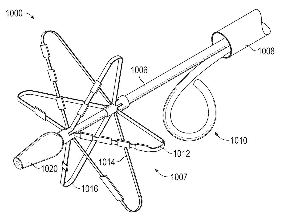
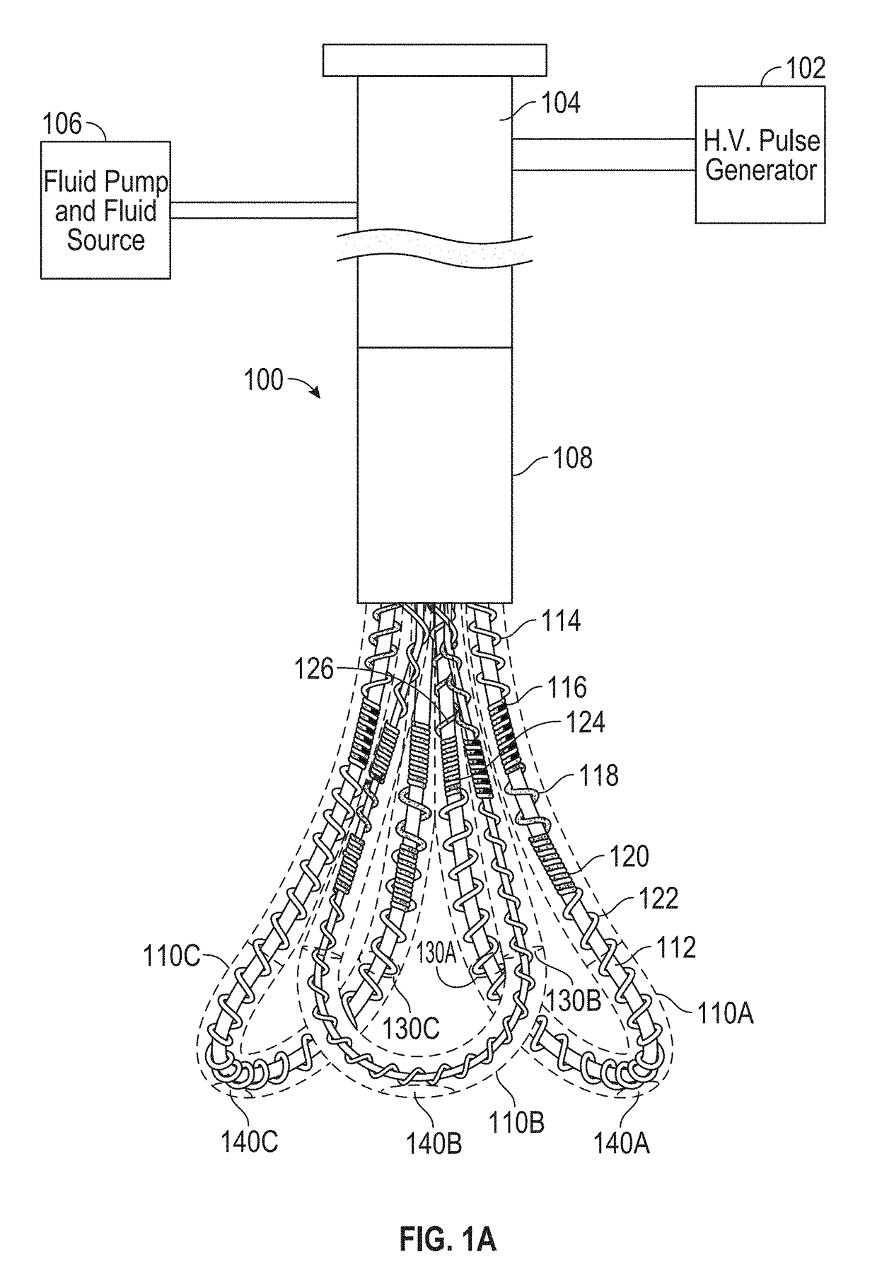
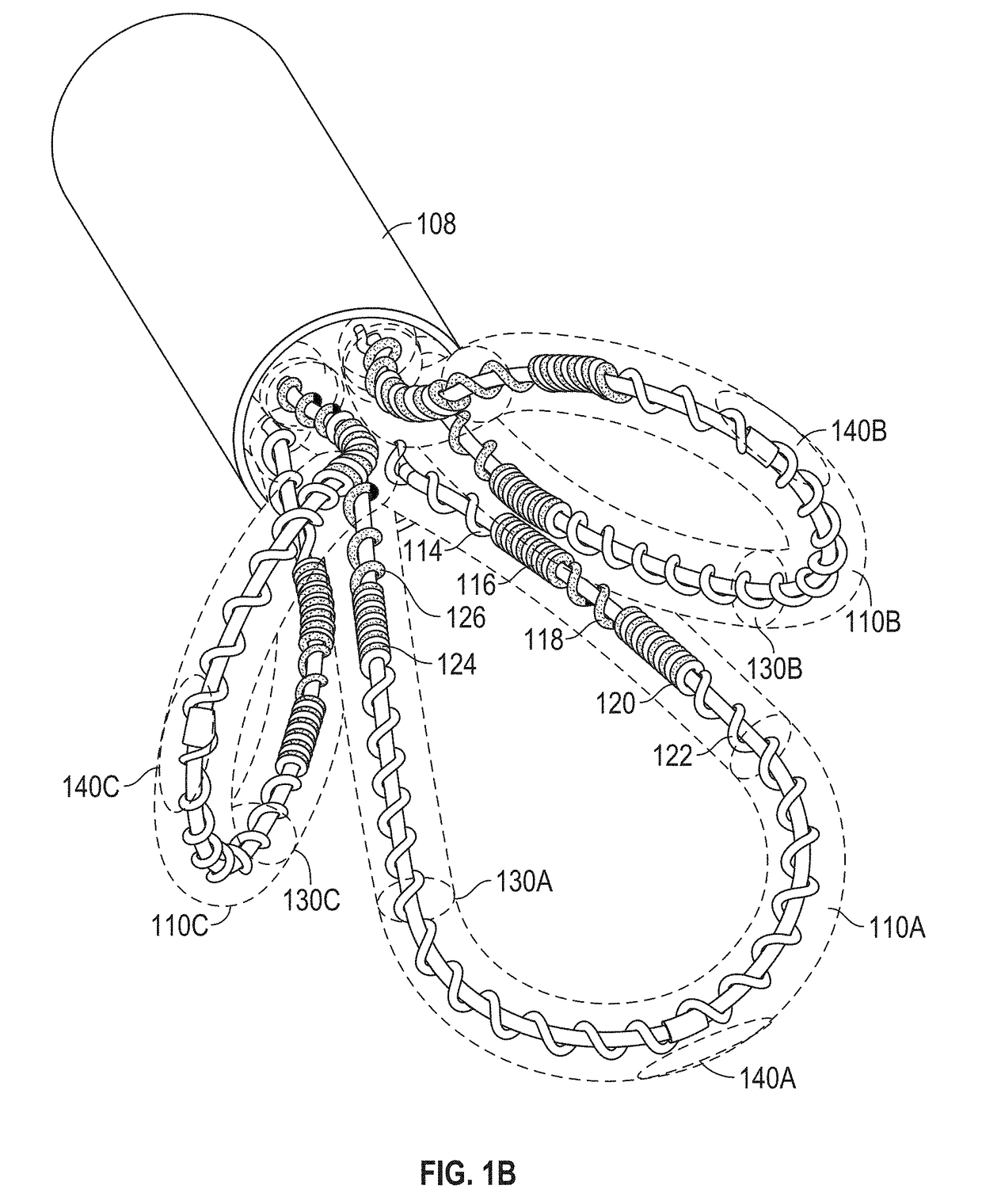
[0031]FIG. 1A schematically depicts one variation of a shock wave device 100 for the treatment of calcified lesions in a heart valve. FIG. 1B schematically depicts exemplary elongated flexible tubes 110A-C carried by a sheath 108. The shock wave device 100 may comprise a first elongated flexible tube 110A, a second elongated flexible tube 110B, and a third elongated flexible tube 110C. As illustrated in FIGS. 1A-1B, the elongated flexible tubes 110A-C may be carried by a sheath 108. At least part of the elongated flexible tubes 110A-C may be movably accommodated within the sheath 108. As illustrated in FIGS. 1A-1B, one or more of the elongated flexible tubes 110A-C may be extended beyond the distal end of the sheath 108 for treating calcified lesions in heart valves. In some variations, the sheath 108 may be coupled to a proximal handle 104. The sheath 108 may be introduced into the vasculature and advanced in a retrograde direction (e.g., via a femoral artery) to a heart valve. The...


PUM


Abstract

Described herein are shock wave devices and methods for the treatment of calcified heart valves. One variation of a shock wave device may comprise an elongated flexible tube carried by a sheath. The tube may have a fluid input end, which may be located near a proximal end of the sheath. The tube may include a loop portion. The loop portion may be configured to be at least partially accommodated within a cusp of the heart valve. The tube may be fillable with a conductive fluid. In some variations, the shock wave device may include an array of electrode pairs associated with a plurality of wires positioned within the loop portion of a tube. The electrode pairs may be electrically connectable to a voltage source and configured to generate shock waves in the conductive fluid in response to voltage pulses.

Description

CROSS-REFERENCE TO RELATED APPLICATIONS[0001]This application claims priority to U.S. Provisional Patent Application No. 62 / 405,002, filed Oct. 6, 2016, which is incorporated herein by reference in its entirety.BACKGROUND[0002]Aortic valve stenosis results in the narrowing of the aortic valve. Aortic valve stenosis may be exacerbated by a congenital defect where the aortic valve has one leaflet (unicuspid) or two leaflets (bicuspid) instead of three leaflets. In many cases, the narrowing of the aortic valve is the result of aortic valve calcification, where calcified plaque accumulates on the leaflets and / or annulus of the aortic valve. For example, calcium plaques deposited on the cusps of the leaflets may stiffen the leaflets, thereby narrowing the valve opening and interfering with efficient blood flow across the aortic valve.[0003]Although research is underway in the development of a replacement aortic valve, one may prefer to soften the leaflets by modifying (e.g., reducing) or...

Claims


Application Information

Patent Timeline
Patent Type & Authority Applications(United States)
IPC IPC(8): A61B17/22
CPCA61B17/22004A61B2017/22098A61B2017/22079A61B17/22012A61B17/22022A61B2017/22025A61B18/26A61B2018/00369A61B2018/2211A61B2018/263A61B2018/266
Inventor BETELIA, RAINIERNGUYEN, HOA D.SAAIBI, CAMILO PEREZ
Owner SHOCKWAVE MEDICAL
Why Eureka
Try Eureka