Shockwave valvuloplasty with multiple balloons

a valvuloplasty and shock wave technology, applied in the field of shock wave valvuloplasty with multiple balloons, can solve the problems of narrowing the valve opening, interfering with the efficient blood flow across the valve, etc., and achieve the effects of softening and/or loosening, reducing the risk of stroke, and removing calcium deposits

Active Publication Date: 2014-02-13
SHOCKWAVE MEDICAL
View PDF8 Cites 44 Cited by
  • Summary
  • Abstract
  • Description
  • Claims
  • Application Information

AI Technical Summary

Benefits of technology

[0004]Described herein are shock wave devices and methods for the treatment of calcified heart valves. The application of shock waves to a calcified region of a valve may help to crack and / or break the calcium deposits, thereby softening and / or loosening and / or removing calcium deposits that stiffen the mechanical properties of the valve. Softening and / or loosening and / or removing calcium deposits may allow the valve to regain at least a portion of its normal function. One variation of a device may comprise at least one balloon that is sized and shaped to fit within a concave portion of a valve cusp when inflated with a liquid and a shock wave source within the balloon. Optionally, a device for treating a calcified heart valve may comprise three balloons that are each sized and shaped to fit within a concave portion of a valve cusp when inflated with a liquid and a shock wave source in each of the three balloons. Each balloon may be separately and / or independently inflatable, and each shock wave source may be separately and / or independently controllable. A shock wave device comprising three balloons and three shock wave sources may be used for treating a tricuspid valve, such as the pulmonary valve and the aortic valve. Shock wave devices comprising one or two balloons and one or two shock wave sources may be used for treating unicuspid, bicuspid and / or tricuspid valves.

Problems solved by technology

For example, calcium plaques deposited on the cusps of the leaflets may stiffen the leaflets, thereby narrowing the valve opening and interfering with efficient blood flow across the valve.

Method used


Image

  • Shockwave valvuloplasty with multiple balloons
  • Shockwave valvuloplasty with multiple balloons
  • Shockwave valvuloplasty with multiple balloons

Examples


Embodiment Construction

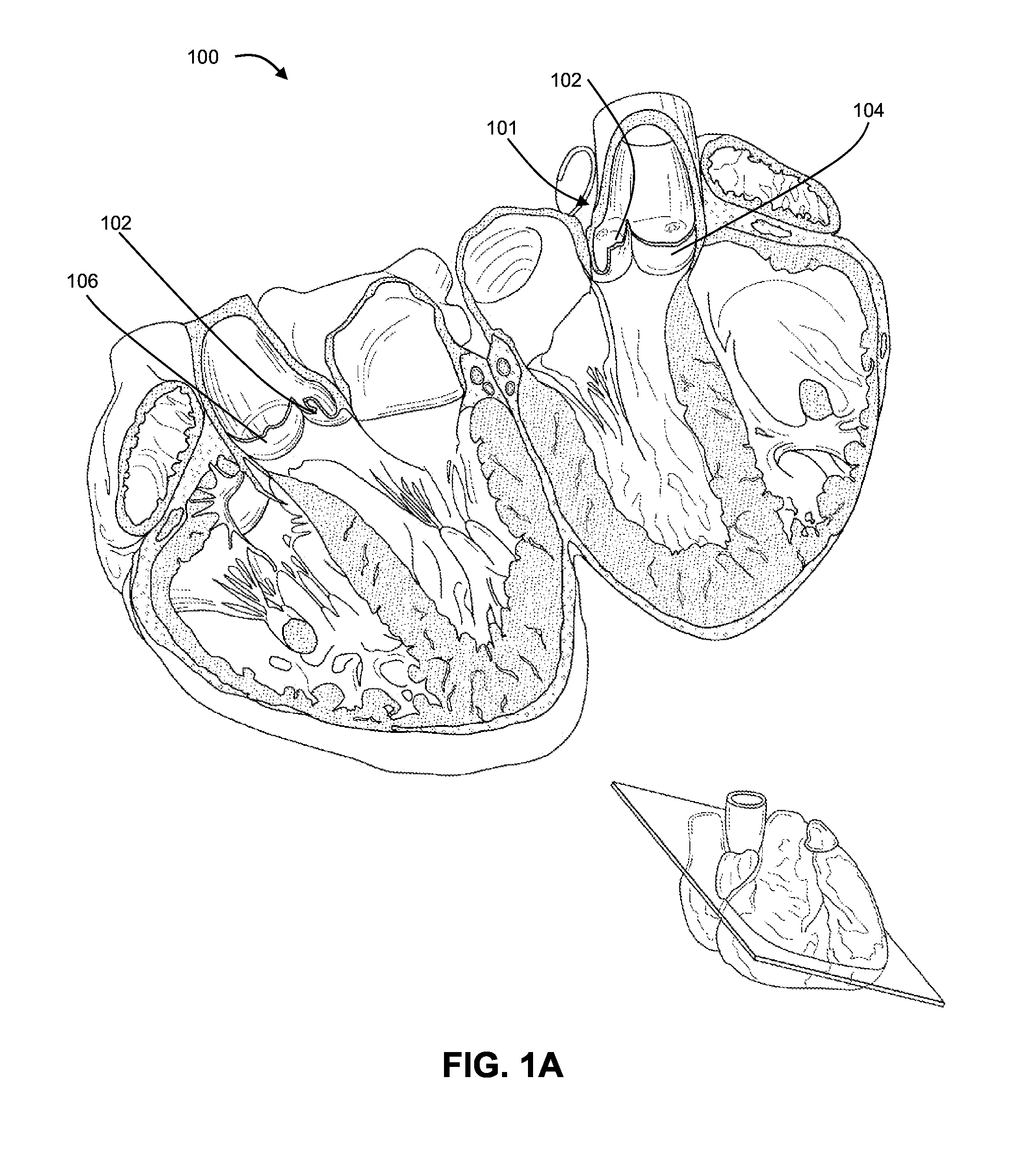
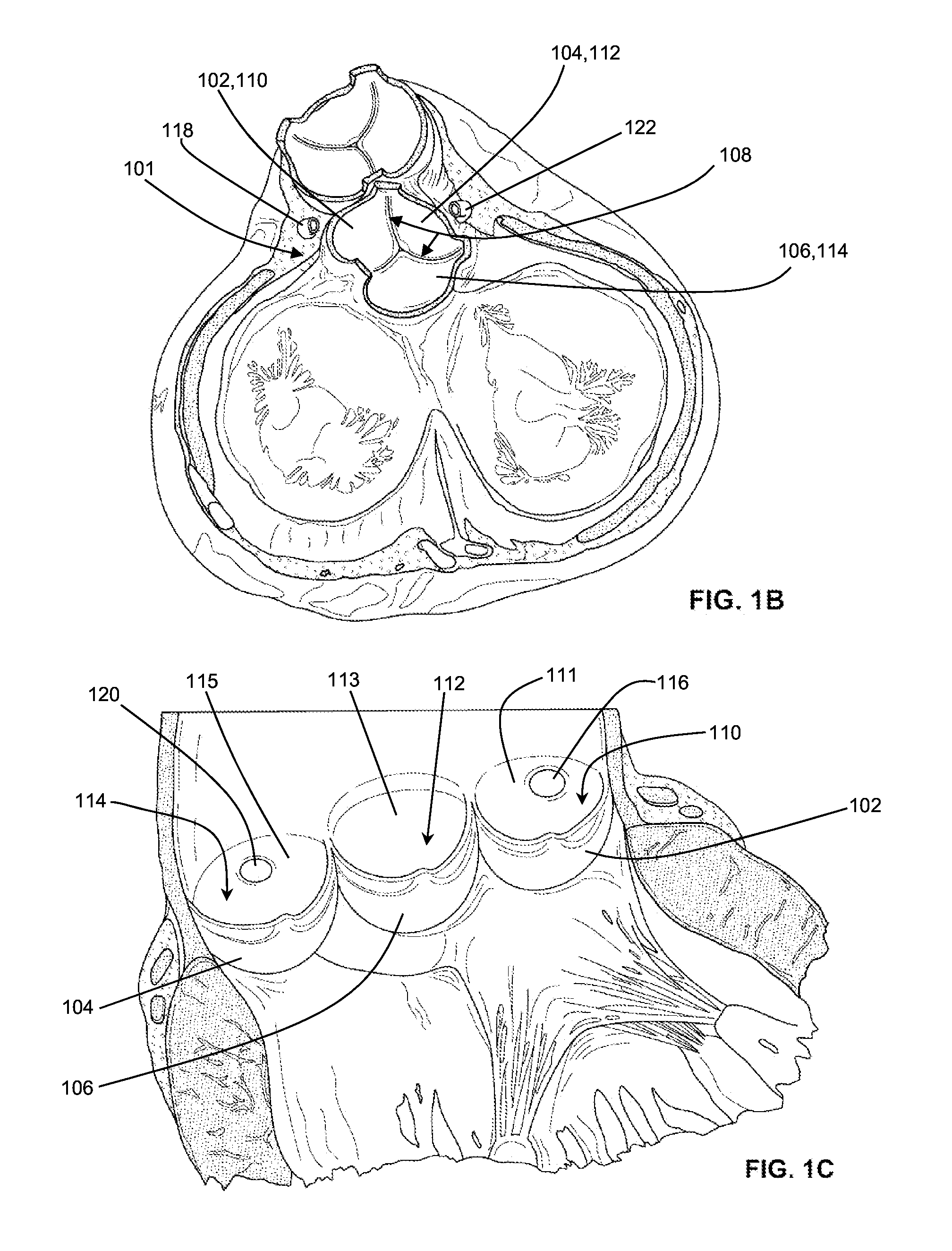
[0018]FIGS. 1A-1C depict various views of the valves of the heart. FIG. 1A is a cross-sectional view of a heart 100 taken along the plane indicated by the inset. The aortic valve 101 comprises a left semilunar leaflet or cusp 102, a right semilunar leaflet or cusp 104 and a posterior semilunar leaflet or cusp 106. Each cusp has a free margin, which articulates with the free margins of the other cusps when the valve closes, and an attached margin that attaches the cusp in a semilunar fashion to the aortic wall. When the aortic valve is closed, the ventricular side of the cusps may have a convex surface and the aortic side of the cusps may have a concave surface. The concave portion of each of the cusps may be bordered by the concave surface of the cusp, the free margin of the cusp, the attached margin of the cusp, and may also include a portion of the valve wall. Alternatively or additionally, the concave portion of each of the cusps may include the aortic sinus associated with each ...


PUM


Abstract

Described herein are shock wave devices and methods for the treatment of calcified heart valves. One variation of a shock wave device includes three balloons that are each sized and shaped to fit within a concave portion of a valve cusp when inflated with a liquid and a shock wave source within each of the three balloons. Each balloon is separately and/or independently inflatable, and each shock wave source is separately and/or independently controllable. Methods of treating calcified heart valves using a shock wave device can include advancing a shock wave device having one or more balloons and a shock wave source in each of the balloons to contact a heart valve, inflating the one or more balloons with a liquid such that the balloon is seated within a concave portion of a valve cusp, and activating the shock wave source.

Description

CROSS-REFERENCE TO RELATED APPLICATIONS[0001]This application claims the benefit of U.S. Provisional Application 61 / 681,068 filed on Aug. 8, 2012, which is hereby incorporated by reference in its entirety.BACKGROUND[0002]Aortic valve stenosis results in the narrowing of the aortic valve. Aortic valve stenosis may be exacerbated by a congenital defect where the aortic valve has one leaflet (unicuspid) or two leaflets (bicuspid) instead of three leaflets. In many cases, the narrowing of the valve is the result of aortic valve calcification, where calcified plaques accumulate on the leaflets and / or annulus of the aortic valve. For example, calcium plaques deposited on the cusps of the leaflets may stiffen the leaflets, thereby narrowing the valve opening and interfering with efficient blood flow across the valve.[0003]Although research is underway in the development of a replacement aortic valve, one may prefer to soften the leaflets by cracking the calcium deposits on the native valve...

Claims


Application Information

Patent Timeline
Patent Type & Authority Applications(United States)
IPC IPC(8): A61B17/22
CPCA61B17/22004A61B17/22012A61B17/22022A61B2017/22098A61B2017/22025A61B2017/22055A61M25/1011A61M29/00A61B17/2202A61B2017/22062
Inventor ADAMS, JOHN M.
Owner SHOCKWAVE MEDICAL
Why Eureka
Try Eureka