Device and Methods for Attaching Sacrificial Anodes

Inactive Publication Date: 2018-04-12
BINGHAM BRYCE RANDAL
View PDF0 Cites 0 Cited by
  • Summary
  • Abstract
  • Description
  • Claims
  • Application Information

AI Technical Summary

Benefits of technology

The present invention is a device with a powerful magnet and a sacrificial anode made of metal with greater electronegativity than the magnet. The magnet is electrically segregated and prevents from being part of any circuit. The magnet pulls the sacrificial anode against an object comprising ferromagnetic metal, called a ferromagnetic object, and thereby maintains a strong physical contact between them. The technical effect of this device is that it provides a way to protect against damage caused by magnetic objects with a simple and effective device.

Problems solved by technology

This current flow corrodes the sacrificial anode.

Method used


Image

  • Device and Methods for Attaching Sacrificial Anodes
  • Device and Methods for Attaching Sacrificial Anodes

Examples


example embodiment

Showing Use

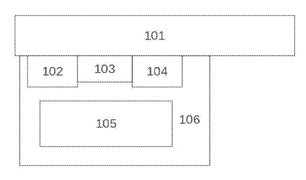
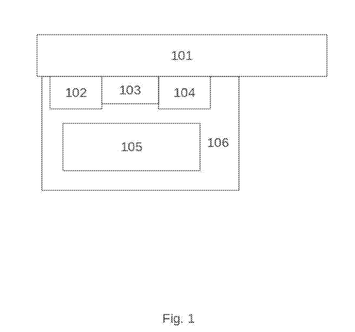
[0057]In an example embodiment the device comprises a metallic wool sacrificial anode, for instance galvanized steel wool. The device is adapted to hold a razor or razor blade comprising ferromagnetic metal, for such times that the razor or razor blade is unused. At such times, if electrolytic moisture is present on the razor blade then the device, the razor blade and the moisture form a circuit, and this prevents the razor blade from corroding.

Other Embodiments

[0058]We show these varied and numerous embodiments of the invention to be exemplary and in no way limiting. Many other embodiments are possible, without departing from the spirit of the invention or sacrificing its advantages.

Advantages and Conclusions

[0059]The device is inexpensive to manufacture, since its component parts—a magnet, metal pieces, and a matrix to tie it all together—are all cheap.

[0060]The device attaches with no trouble to any plate of ferromagnetic metal. There is no need of tooling or manufactu...


PUM


Abstract

A sacrificial anode contains a powerful magnet which pulls it against an object comprising ferromagnetic metal and thus fastens the anode to the ferromagnetic metal. The magnet itself is encased in an electrically inert substance and thus does not corrode.

Description

PRIORITY[0001]This disclosure claims the priority of U.S. Ser. No. 62 / 240,535 filed on Oct. 13, 2015, the contents of which are wholly included herein.FIELD OF INVENTION[0002]This pertains to the field of protection of iron, nickel and steel from corrosion.BACKGROUND[0003]Corrosion in iron, steel, nickel and other ferromagnetic metals is accelerated by the presence of an electrolytic solution. Heat accelerates the reaction causing this corrosion but is not essential to it. The reaction happens because the ferromagnetic metal and water form part of a circuit where part of the ferromagnetic metal becomes the anode, and part of the ferromagnetic metal becomes the cathode. The ferromagnetic metal in the anode gives up its electrons, which migrate to the cathode. Simultaneously at the anode ions of the ferromagnetic metal break free into the electrolyte and combine with the H2O—to form rust.[0004]A common way to prevent corrosion in an object made of ferromagnetic metal is to use sacrifi...

Claims


Application Information

Patent Timeline
IPC IPC(8): C23F13/18C23F13/14
CPCC23F13/14C23F13/18B63B59/04C23F13/06C23F2213/31B26B21/4087B26B21/54
Inventor BINGHAM, BRYCE RANDAL
Owner BINGHAM BRYCE RANDAL
Why Eureka
Try Eureka