Apparatus and methods for the optimal stitch zone calculation of a generated projection of a spherical image
- Summary
- Abstract
- Description
- Claims
- Application Information
AI Technical Summary
Benefits of technology
Problems solved by technology
Method used
Image
Examples
first embodiment
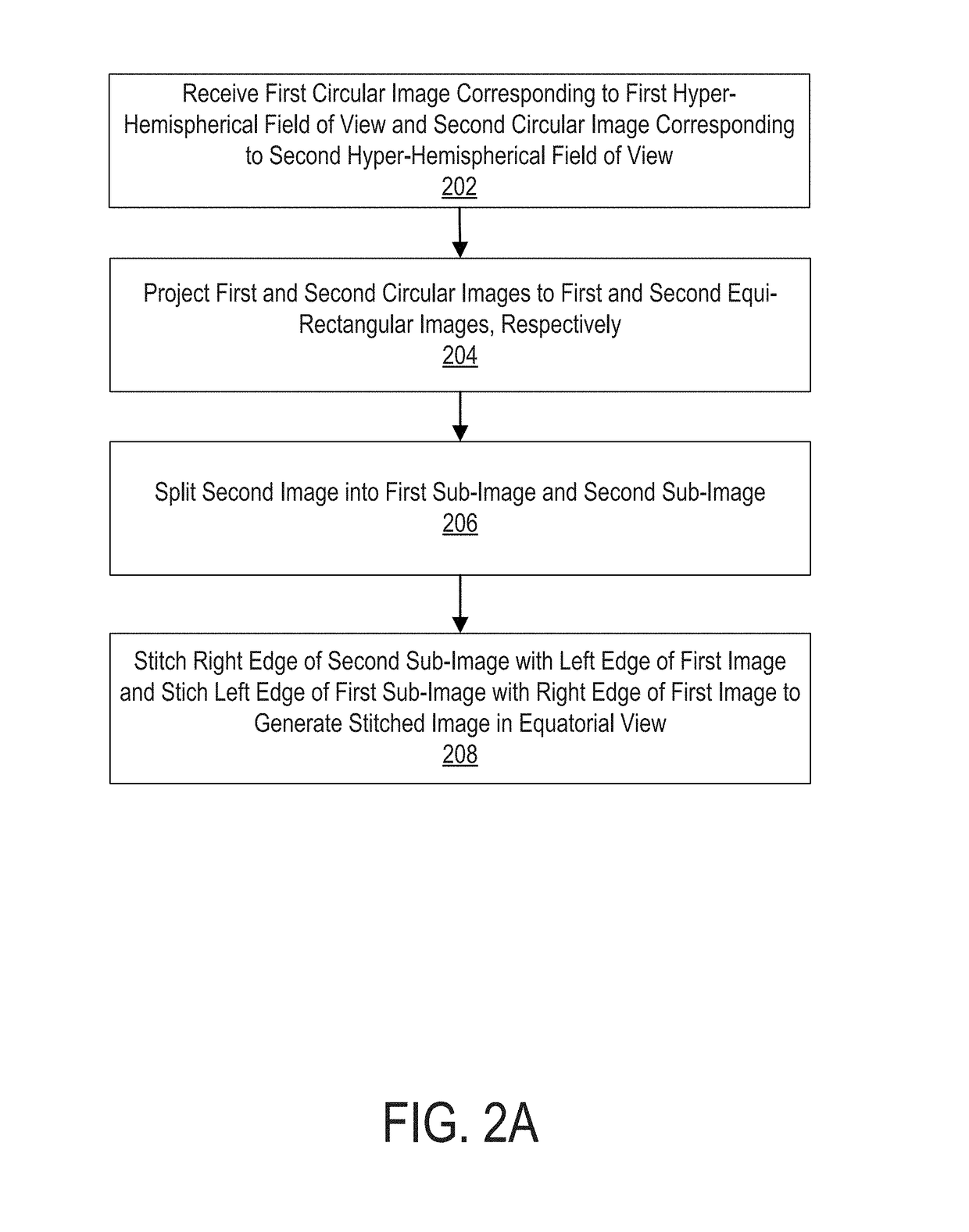
[0055]FIG. 2A illustrates a process for stitching images captured by a spherical camera system 100 where the stitching zone runs along a meridian zone of the spherical image, while FIG. 2B illustrates example images resulting from the process of FIG. 2A. FIGS. 2A and 2B are described together for clarity and convenience.
[0056]Referring now to FIG. 2A, at step 202, an image sensor receives a first circular image corresponding to a first hyper-hemispherical field of view and a second circular image corresponding to a second hyper-hemispherical field of view. For example, as shown in FIG. 2B, a first circular image (e.g., image “A”) 250 and a second circular image (e.g., image “B”) 260 may be received at a video processing system. The first circular image 250 may represent, for example, the field of view captured by a first camera 110 (e.g., a front-facing camera) of a spherical camera system 100 and the second circular image 260 may represent, for example, the field of view captured b...
second embodiment
[0062]FIGS. 3A and 3B illustrate a process for stitching images in a spherical camera system 100 where the stitching zone now runs along the equatorial zone of the spherical image (as opposed to the meridian zone as shown in FIGS. 2A and 2B), while FIG. 3B illustrates example images resulting from the process of FIG. 3A. In other words, the stitching methodology of FIG. 3A only utilizes a single stitch line. FIGS. 3A and 3B are described together for clarity and convenience.
[0063]A first circular image 350 and a second circular image 360 may be received at step 302 at a video processing system, which may be similar to the first circular image 250 and second circular image 260 respectively discussed above. The first circular image 350 and the second circular image 360 may be projected at step 304 to a first rectangular image 352 and a second rectangular image 362 respectively. Here, instead of using a conventional equirectangular projection, a projection may instead be used in which ...
PUM
 Abstract
Description
Claims
Application Information
 - R&D
- Intellectual Property
- Life Sciences
- Materials
- Tech Scout
- Unparalleled Data Quality
- Higher Quality Content
- 60% Fewer Hallucinations
Browse by: Latest US Patents, China's latest patents, Technical Efficacy Thesaurus, Application Domain, Technology Topic, Popular Technical Reports.
© 2025 PatSnap. All rights reserved.Legal|Privacy policy|Modern Slavery Act Transparency Statement|Sitemap|About US| Contact US: help@patsnap.com


