Workpiece loader device

a loader and workpiece technology, applied in the direction of computer control, program control, instruments, etc., can solve the problems of requiring much more effort in teaching work, and requiring longer teaching tim

Active Publication Date: 2018-04-19
DMG MORI SEIKI CO LTD
View PDF5 Cites 2 Cited by
  • Summary
  • Abstract
  • Description
  • Claims
  • Application Information

AI Technical Summary

Benefits of technology

[0008]The disclosed embodiments of the present invention have been developed in view of the above-mentioned and/or other problems in t

Problems solved by technology

Therefore, the problems were that the dial gauge was required for the teaching, and the teaching work was required much more effort, and the t

Method used


Image

  • Workpiece loader device
  • Workpiece loader device
  • Workpiece loader device

Examples


embodiment 1

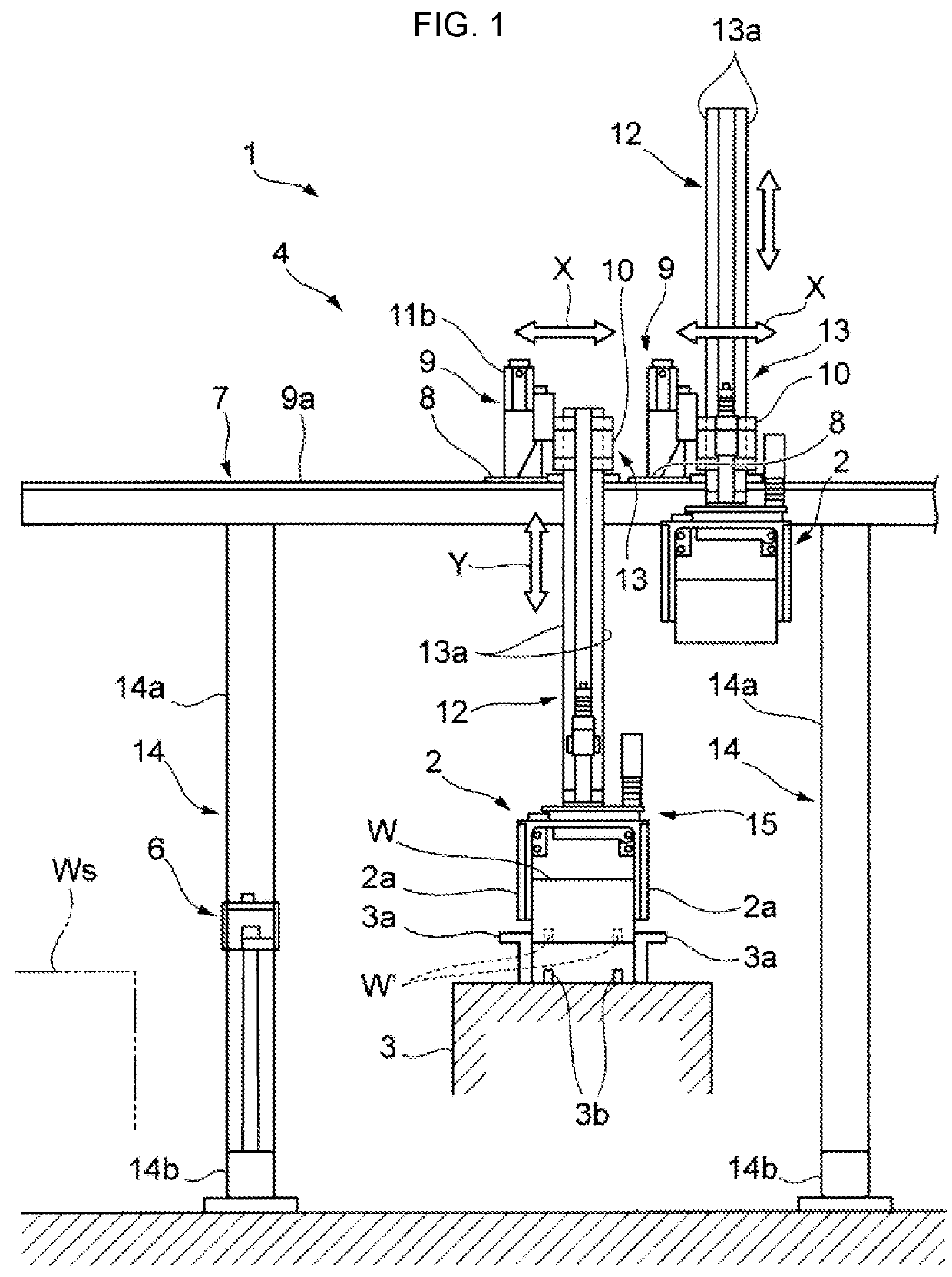
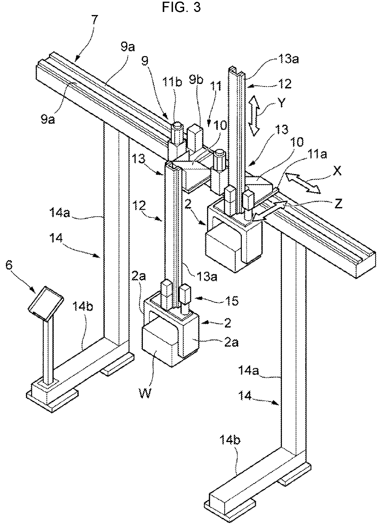
[0029]FIGS. 1 to 5 are the illustrations to describe the workpiece loader device according to embodiment 1 of the present invention.

[0030]In the drawing, reference numeral 1 denotes a workpiece loader device according to embodiment 1. The workpiece loader device 1 is provided with a loader mechanism 4 which moves a loader hand 2 holding a workpiece W between a workpiece storage part WS and a workpiece receiving position on a workpiece table 3 of the machine tool, and a loader mechanism control part 5 which controls the loader mechanism 4 so as to move the loader hand 2 to a predetermined workpiece receiving position.

[0031]In the workpiece table 3, a plurality of positioning pins 3b, 3b are provided for positioning a workpiece W. Further, in the workpiece table 3, clamp claws 3a, 3a are arranged to clamp the workpiece after being positioned.

[0032]Here, in a case of embodiment 1, the workpiece receiving position means a position where the position pins 3b, which are provided on the wo...

embodiment 2

[0051]In embodiment 1, the X, Y, Z coordinates in the state in which the positioning pins 3b of the workpiece table 3 are engaged with the positioning holes W′ of the workpiece W is defined as the workpiece receiving position coordinates, but the workpiece receiving position coordinates of the present invention are not limited to them.

[0052]FIG. 6 is an illustration showing embodiment 2 in a case in which a workpiece is received in a chuck (clamp mechanism) 31 mounted in a spindle of a lathe. The chuck 31 has three clamp claws 31a, 31b, 31c which are arranged at equal angle interval and are movable in a radial direction. Even if the workpiece W is set in a position shifted from the shaft center a of the spindle within the region (position where it is possible to clamp) surrounding by the three clamp claws 31a to 31c (see the solid line in FIG. 6), it is configured to automatically adjust the position of the workpiece W to the center, which corresponds to the shaft center a of the sp...


PUM


Abstract

In a workpiece loader device, a loader mechanism is configured to move a loader hand directly held by operator's hands to a desired position. A loader mechanism control part stores position coordinates as workpiece receiving position coordinates when the loader hand is moved by operator's hands to the workpiece receiving position and a completion of moving is confirmed.

Description

CROSS-REFERENCE TO RELATED APPLICATIONS[0001]This is the U.S. National Phase under 35 U.S.C. 371 of International Application No. PCT / JP2016 / 56987, filed on Mar. 7, 2016, which in turn claims the benefit of Japanese Patent Application No. 2015-072171, filed on Mar. 31, 2015, the disclosures of which are incorporated by reference herein.BACKGROUND OF THE INVENTIONField of the Invention[0002]The present invention relates to a workpiece loader device, which supplies an unmachined workpiece to a machine tool such as a lathe, a machining center, etc., and conveys a machined workpiece from the machine tool, and more specifically, relates to an improvement of a teaching structure in order to teach a receiving position of a workpiece.Description of the Related Art[0003]For example, in a case in which an NC lathe or a machining center, which is provided with a gantry-type workpiece loader device, is newly installed, it is necessary to perform a teaching work to the workpiece loader device so...

Claims


Application Information

Patent Timeline
IPC IPC(8): B23Q7/04B25J9/02G05B19/423
CPCB23Q7/045B25J9/023B23Q7/046G05B19/423G05B2219/36425G05B2219/36492B23Q7/04B25J9/0081B25J9/026B25J9/1633B25J9/1664B25J13/02B25J13/08B25J15/0253B23Q1/626
Inventor YASUDA, HIROSHIOKUYAMA, YOSHINOBUHIGUCHI, TAKAYUKI
Owner DMG MORI SEIKI CO LTD
Why Eureka
Try Eureka