

Systems and methods for in-field stereocamera calibration
a stereocamera and calibration system technology, applied in the field of surveillance, can solve the problems of difficult to satisfy with pure hardware solutions, inaccurate positioning of lenses, imaging imperfections, etc., and achieve the effect of convenient installation
- Summary
- Abstract
- Description
- Claims
- Application Information
AI Technical Summary
Benefits of technology
Problems solved by technology
Method used
Image

Examples
Embodiment Construction
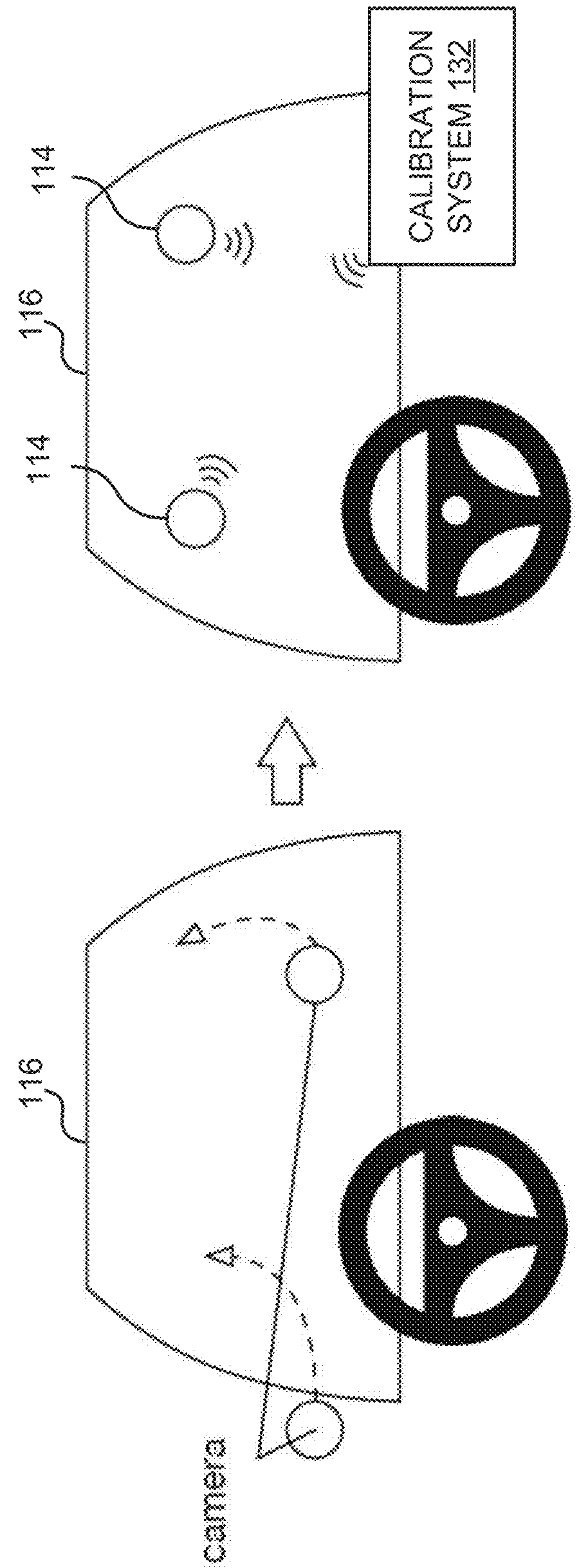
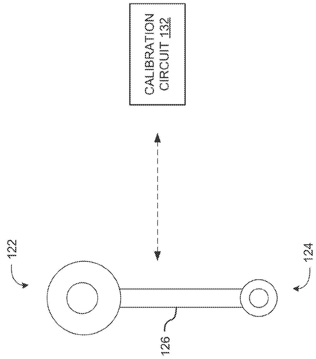
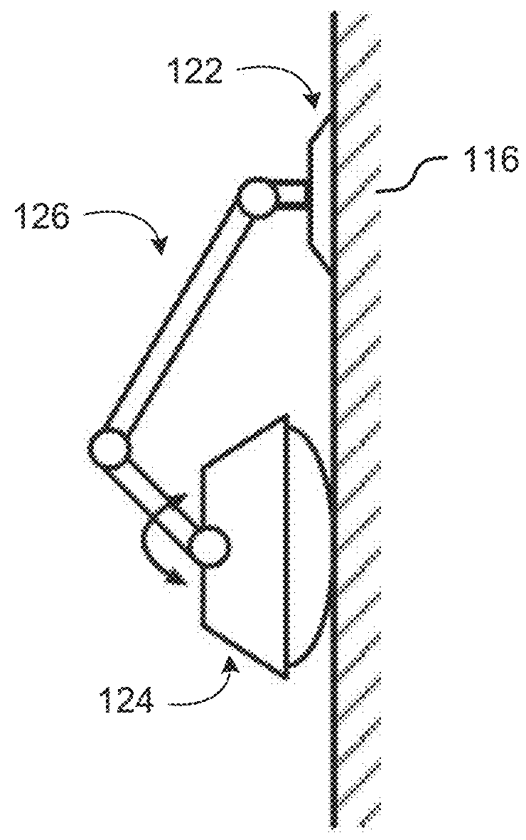
[0008]Embodiments disclosed herein provide systems and methods for stereo camera calibration that can be used to calibrate stereovision cameras in the field. As a result of in-field calibration, contrary to conventional wisdom, the cameras within a stereocamera system do not have to be rigidly mounted together, and can be installed independently. This allows the system to be more easily installed in a diverse set of applications and orientations, and allows the same stereocamera system to be used for a plurality of baselines. However, independent camera mounting can be more susceptible to changes in mechanical orientation.
[0009]Conventionally, stereopairs were rigidly mounted together because the stereopair calibration was heavily dependent on the mechanical orientation of the cameras (e.g., the relative camera positions)—if the cameras shifted relative to each other, the calibration would be lost. This shift is particularly prevalent in applications where the system is translating ...
PUM
 Abstract
Description
Claims
Application Information