Generating and Displaying a Computer Generated Image on a Future Pose of a Real World Object

a computer generated image and real-world object technology, applied in the direction of generating/distributing signals, instruments, optical elements, etc., can solve the problems of inaccurate display of virtual objects, lack of precise resolution, and signal degradation of physical object tracking systems toward the limits of transmission rang

Active Publication Date: 2018-04-19
MICROSOFT TECH LICENSING LLC
View PDF19 Cites 134 Cited by
  • Summary
  • Abstract
  • Description
  • Claims
  • Application Information

AI Technical Summary

Problems solved by technology

However, some conventional controllers lack precise resolution and users end up with choppy, inaccurate display of the virtual objects.
Further, these physical object tracking systems often experience signal degradation toward the limits of the transmission range in addition to interference from other objects and energy sources in the environment.
In the face of such degradation, the accuracy of the tracking system can become completely unreliable under various circumstances, which negatively impacts the interactive experience for the user.
Further still, they often report position within one zone at a time, which can lead to problems when the object is moved between zones while temporarily located beyond the range of the tracking system.

Method used


Image

  • Generating and Displaying a Computer Generated Image on a Future Pose of a Real World Object
  • Generating and Displaying a Computer Generated Image on a Future Pose of a Real World Object
  • Generating and Displaying a Computer Generated Image on a Future Pose of a Real World Object

Examples


Embodiment Construction

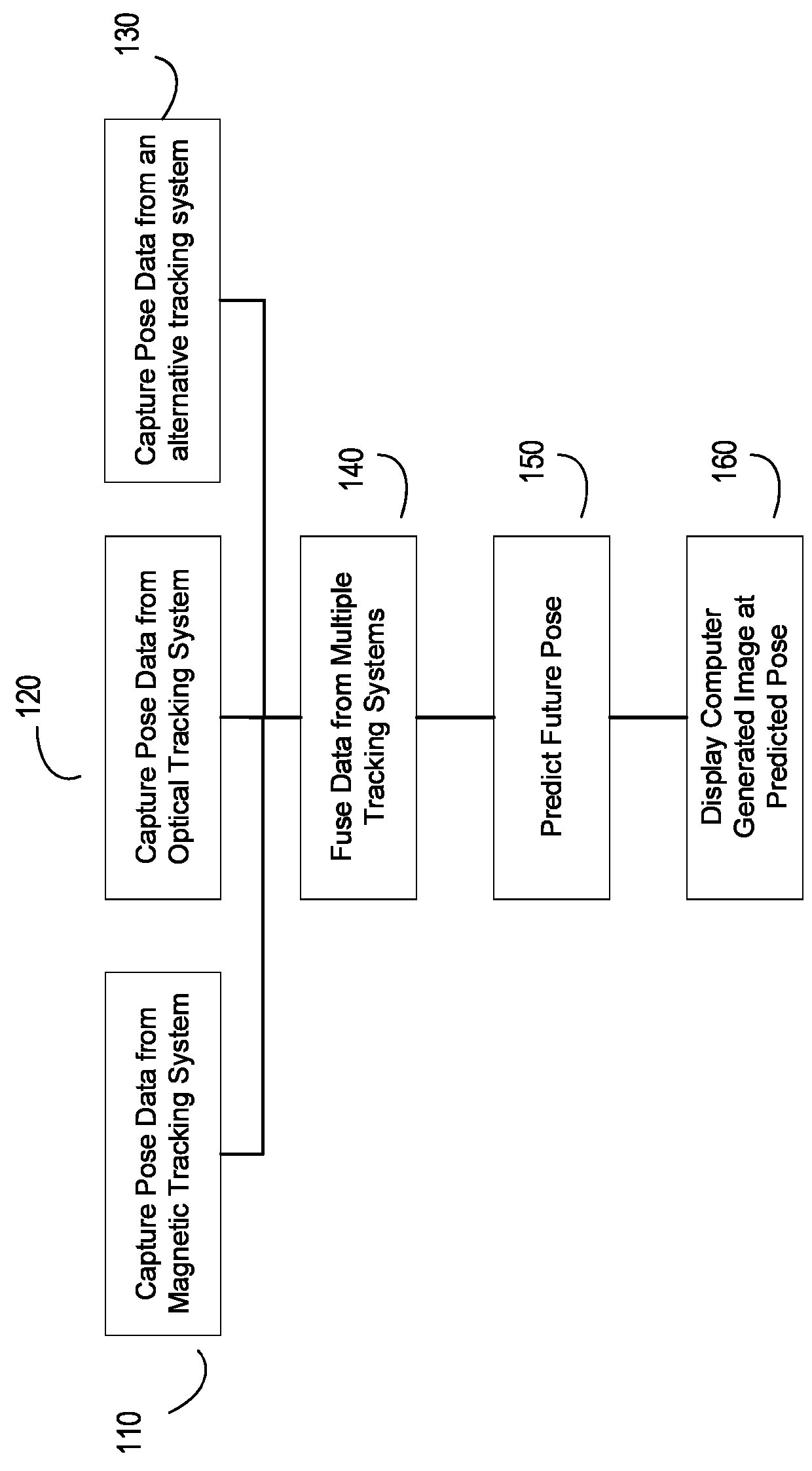
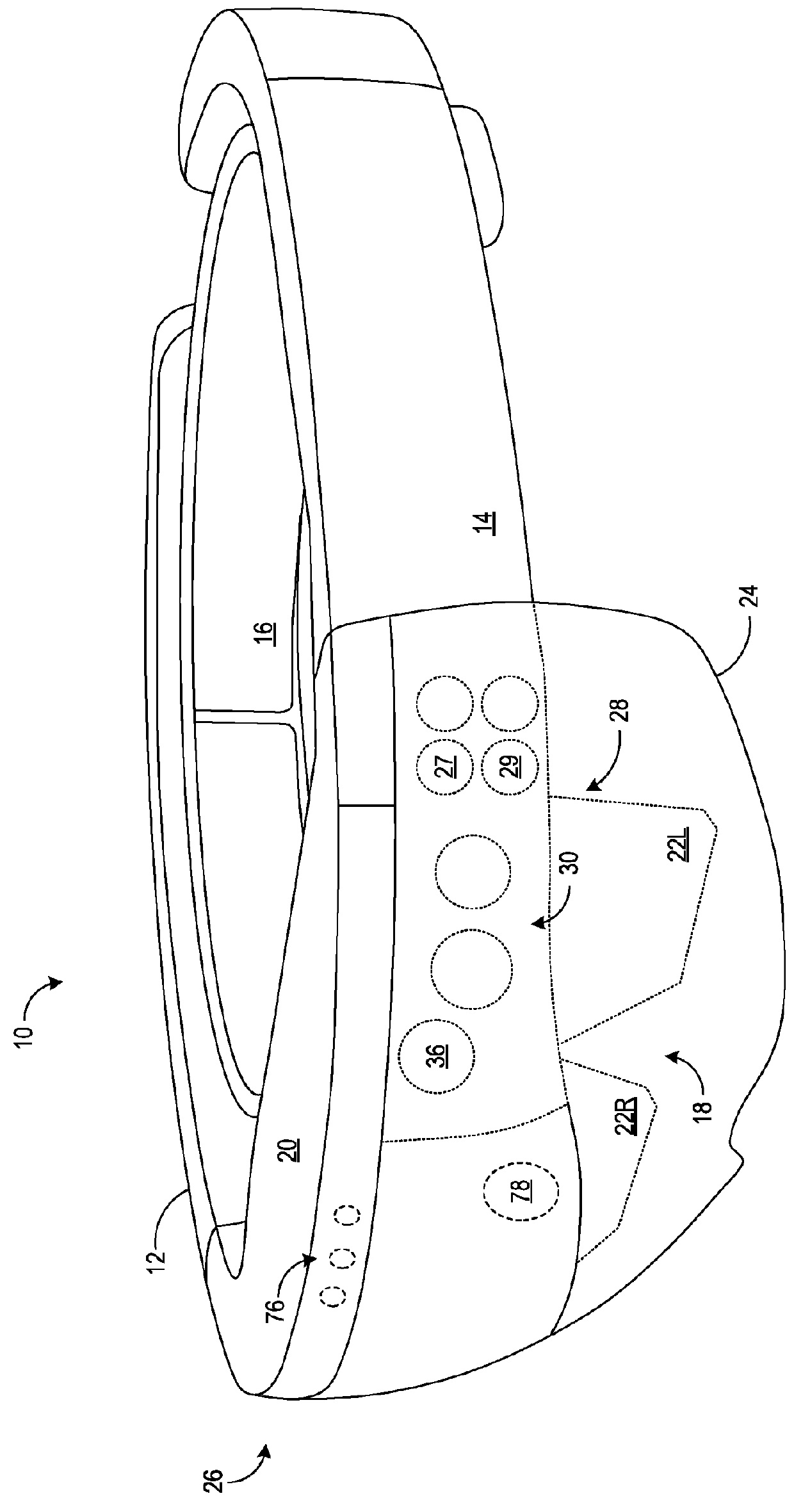
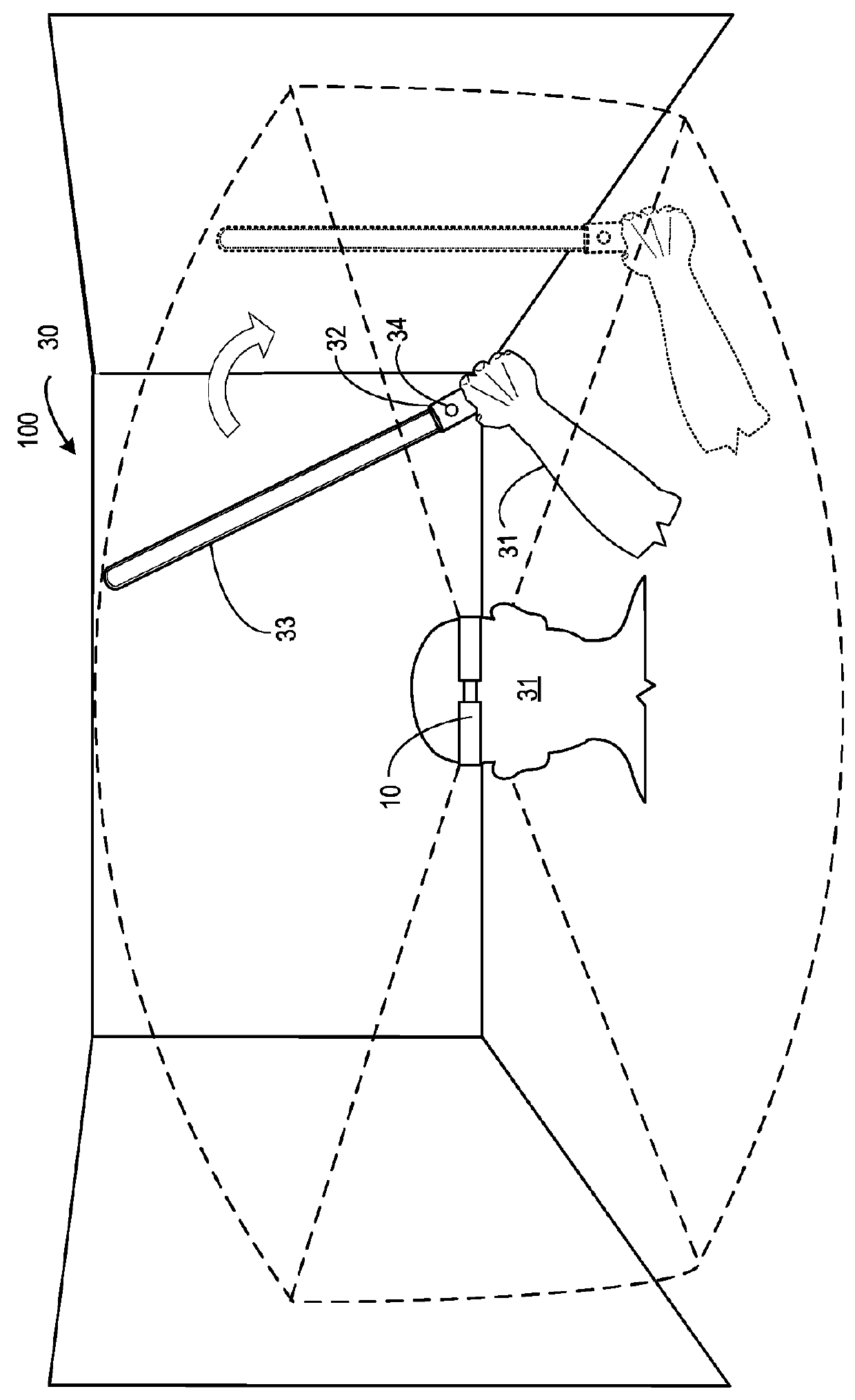
[0023]Some embodiments herein implement a solution that allow a mixed reality system to fuse data from two or more tracking systems to determine the location, orientation, velocity, and acceleration of a real-world object. In one embodiment, a system for displaying a computer generated image corresponding to the pose of a real-world object in a mixed reality system. The system may comprise a head-mounted display (HMD) device. The system may further comprise a magnetic tracking system configured to detect the pose of the object, the magnetic tracking system comprising a base station configured to emit an electromagnetic field (EMF) and an EMF sensor configured to sense the EMF. The system may further comprise a second tracking system configured to detect the pose of the object. The data derived from the magnetic tracking system and the data derived from the second tracking system may be synchronized in time.

[0024]An alternate embodiment implements a solution to enable a mixed reality...


PUM


Abstract

Methods and systems for displaying a computer generated image corresponding to the pose of a real-world object in a mixed reality system. The system may include of a head-mounted display (HMD) device, a magnetic track system and an optical system. Pose data detected by the two tracking systems can be synchronized by a timestamp that is embedded in an electromagnetic field transmitted by the magnetic tracking system. A processor may also be configured to calculate a future pose of the real world object based on a time offset based on the time needed by the HMD to calculate, buffer and generate display output and on data from the two tracking systems, such that the relative location of the computer generated image (CGI) corresponds with the actual location of the real-world object relative to the real world environment at the time the CGI actually appears in the display.

Description

BACKGROUND[0001]Recently, various technologies have emerged that allow users to experience a blend of reality and virtual worlds along a mixed reality continuum. For example, head-mounted display (HMD) devices may include various sensors that allow the HMD device to display a blend of reality and virtual objects on the HMD device as augmented reality, or block out the real world view to display only virtual reality. Whether for virtual or augmented reality, a closer tie between real-world features and the display of virtual objects is often desired in order to heighten the interactive experience and provide the user with more control.[0002]One way to bring real-world features into the virtual world is to track a handheld controller through space as it is being used. However, some conventional controllers lack precise resolution and users end up with choppy, inaccurate display of the virtual objects. Some handheld controllers even require externally positioned cameras, tethering use ...

Claims


Application Information

Patent Timeline
Patent Type & Authority Applications(United States)
IPC IPC(8): G06T19/00G06F1/14G06F3/03G02B27/01
CPCG06T19/006G06F1/14G02B2027/014G02B27/0172G06T7/004G06F3/0304G06F3/012G06F3/0346A61B2090/365G06T7/70G06F3/017G06F3/011
Inventor TOMLIN, ARTHURPOULOS, ADAM GABRIELBROWN, CAMERON GRAEME
Owner MICROSOFT TECH LICENSING LLC
Why Eureka
Try Eureka