
System and method for detecting multiple fragments in a target missile

Active Publication Date: 2018-04-26
INVOCON
View PDF0 Cites 10 Cited by
  • Summary
  • Abstract
  • Description
  • Claims
  • Application Information

AI Technical Summary

Benefits of technology

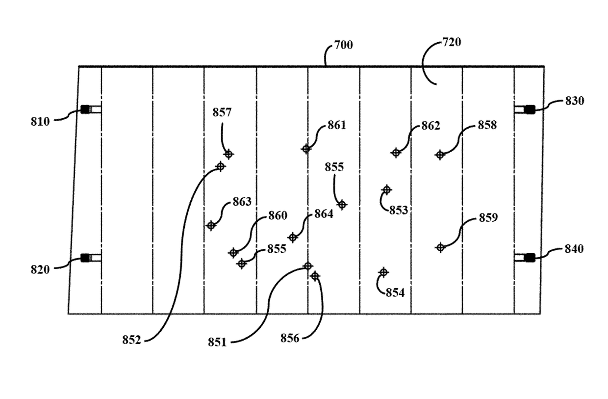
The present invention aims to locate the impact of multiple fragments from an explosion on a target. It uses sensors placed on the target to capture the acoustic signals generated by the fragments and estimates their locations in time using a detection system. Additionally, the invention can provide additional information about the fragment impact that may be useful when combining the outputs of multiple sensors.

Problems solved by technology

However, in a “Shrapnel Kill” environment, each target missile may take many hits from the shrapnel generated from the explosion of the warhead from the kill vehicle.
Conventional wire / optical grids ignore a wire or optical path when it is broken rendering it useless, thus, it is impossible utilizing current lethality assessment methods to accurately record multiple random hits from shrapnel on a grid because once a path is broken by one hit, future hits, involving that conductive path, are not detected and, as a result, would create incorrect tabulation of the multiple hits from the shrapnel kill vehicle.
While the prior art methods have merit, they do not convey sufficiently the trajectory of the shrapnel hits upon the ballistic target threat.
Moreover, the prior art does not provide the ability to determine accurately multiple impacts on a target per unit of time.
Finally, the prior art does not determine adequately the location of those impacts on the target.

Method used


Image

  • System and method for detecting multiple fragments in a target missile
  • System and method for detecting multiple fragments in a target missile
  • System and method for detecting multiple fragments in a target missile

Examples


Embodiment Construction

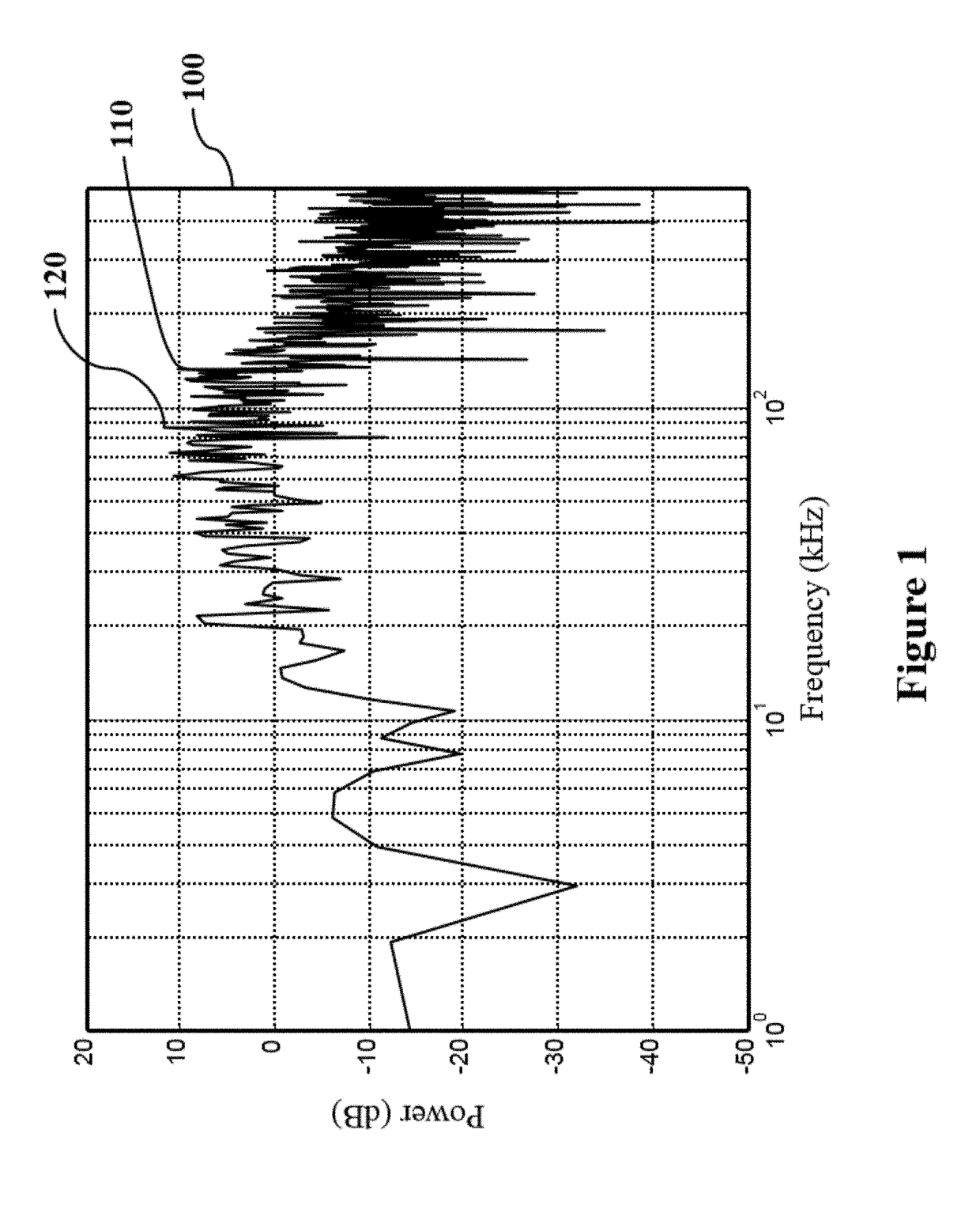
[0026]The detector of the present invention is in the form of a digital signal processing algorithm that operates on digital samples of sensor responses captured by, but not limited to, a WKIPS system. The detector of the present invention reliably detects fragment impacts; functions autonomously; operates on a signal serially in time; does not require multiple passes over the signal samples to produce detections; functions without customization to individual sensors; generates information about the detected impact; and is independent of input signal strength.

Description of the Detector

Theory

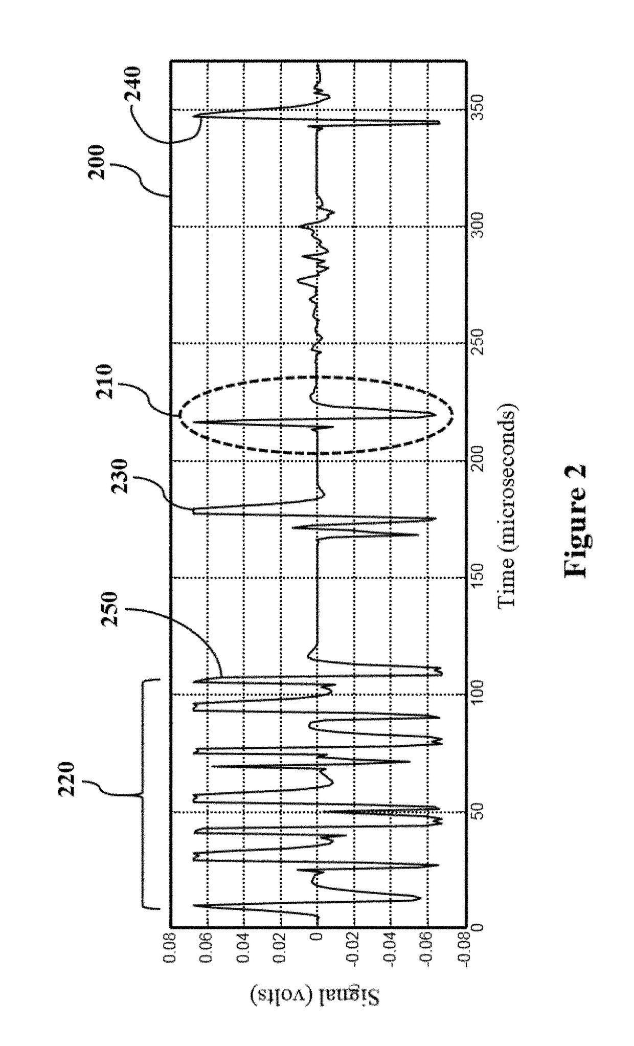
[0027]The model of the physics of the situation is built upon the idea of numerous fragments colliding with the target and each providing a signal due to its impact. The recorded signal is the sum of all fragment signals.

[0028]This situation can be compared to a multiuser communication problem. Each fragment's signal is an attempt by a user (fragment) to communicate to a receiver (WKIPS sensor)....


PUM


Abstract

A system and method is provided for detecting the trajectory of multiple fragments through a conic or cylindrical section, such as the body of a missile. Three or more sensors are placed on the on the body of the object. Each of the sensors is constructed and arranged to measure signals to the sensor at from impacts on one or more locations on the body. The sensor then transmits a signal commiserate with the impact of a fragment thereon. A computer system is also provided to perform necessary calculations and, potentially, record the impact times and locations. When the body of the object is hit by fragments or shrapnel, a signal from one or more of the sensors is sent to the computer system. This operation is performed and constantly updated for all locations where a fragment is detected by one or more of the sensors. Waveforms of the impacts are recorded, but because multiple hits can occur, there can be superposition (or destruction) of the resulting waveform sent to the computer system. The computer system can interpret which superposition or destruction is indicative of another fragment strike, and filter out those additions or subtractions to the waveforms that could not possibly be from another fragment.

Description

CROSS-REFERENCE TO RELATED APPLICATIONS[0001]This application is a conversion of U.S. Provisional Patent Application No. 62 / 407,463 with the same title and from the same inventors as the present application, the aforesaid provisional application having been filed on Oct. 12, 2016, and which is incorporated herein by reference for all purposes.STATEMENT REGARDING FEDERALLY SPONSORED RESEARCH[0002]This invention was not funded or sponsored by the federal government.BACKGROUND OF THE INVENTION1. Field of the Invention[0003]The present invention relates to anti-ballistic missiles. More specifically, the present invention relates to a method and system for detecting when fragments emanating from an anti-ballistic missile strikes a target missile in order to determine the effectiveness of the anti-ballistic missile.2. Description of the Related Art[0004]The Department of Defense (DOD) of the U.S. government has developed anti missile technology to protect the United States and allied inte...

Claims


Application Information

Patent Timeline
IPC IPC(8): G01N29/04F41G7/00G01L5/14F42B12/22
CPCG01N29/04F41G7/007G01L5/14F41G7/001F42B12/22F41G7/224G01N29/045G01N29/09G01N29/4472F41J5/06F42B35/00
Inventor CHAFFEE, DONALD L.HEERMANN, DOUGLAS A.PHILPOT, BRIAN D.
Owner INVOCON
Learn More