
Light emitting and receiving system

Active Publication Date: 2018-04-26
STANLEY ELECTRIC CO LTD
View PDF4 Cites 3 Cited by
  • Summary
  • Abstract
  • Description
  • Claims
  • Application Information

AI Technical Summary

Benefits of technology

The present invention provides a technology that can make a light emitting and receiving system smaller, simpler, and cheaper while also making the receiving light beams more uniform.

Problems solved by technology

Therefore, in order to ensure sufficient quantity of light from the reflected light beam, use of a large number of MEMS devices is required, thereby causing a cost increase due to an increase in the number of parts.
Also, in many occasions, since there is dispersion in performance among the multiple MEMS devices, it is difficult to adjust the dispersion among the devices and receive light beams in a desired state.
Further, the use of a reflective optical system causes the optical system to become complicated which also makes it difficult to miniaturize the system.

Method used


Image

  • Light emitting and receiving system
  • Light emitting and receiving system
  • Light emitting and receiving system

Examples


Embodiment Construction

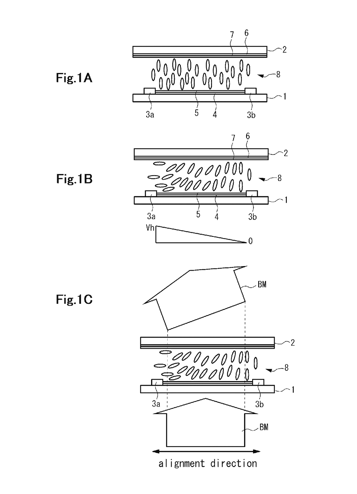
[0029]FIGS. 1A-1C are schematic cross sectional views to describe the basic structure and the operation principle of the liquid crystal element used in one embodiment of the light emitting and receiving system. In the liquid crystal element shown in FIG. 1A, a liquid crystal layer 8 is provided between a pair of substrates 1, 2 (transparent substrates) disposed opposite each other. And on one surface side of the substrate 1 is disposed a pair of electrodes 3a, 3b, a high-resistance film 4 provided between these electrodes 3a, 3b and connected thereto, and an alignment film 5 provided at least on the upper area of the high-resistance film 4. On one surface side of the substrate 2 is disposed a common electrode 6 provided to the area at least opposing each of the electrodes 3a, 3b and the high-resistance film 4, and an alignment film 7 provided at least on the upper area of the common electrode 6.

[0030]In the example shown in the figure, each of the alignment films 5, 7 is a vertical ...


PUM


Abstract

To reduce the size, simplify the structure of a light emitting and receiving system. The system that detects a target object with the use of reflected lights gained from a light irradiated to the target object includes a flat-plate shaped light control apparatus having light control parts, a light-entry apparatus allowing light to enter into a light control part, a light-receiving apparatus that receives emitting lights from the remaining light control parts, a control apparatus that controls the light-entry apparatus and the light-receiving apparatus and detects the target object. The light control apparatus includes liquid crystal elements supporting light control parts between a pair of substrates and a drive unit to drive the liquid crystal elements. Each of the light control parts includes a pair of electrodes, a high-resistance film disposed between the electrodes, and a liquid crystal layer disposed at least to the region overlapping the high-resistance film.

Description

BACKGROUND OF THE INVENTIONField of the Invention[0001]The present invention relates to a technique for detecting the distance and the location, etc. of a target object.Description of the Background Art[0002]German Patent DE102011113147B3 (Application number: DE201110113147) teaches a light emitting and receiving system capable of controlling the direction of the advancing light using multiple MEMS (Micro Electro Mechanical Systems) devices. In the light emitting and receiving system, measuring distance to a target object or detecting the position of the target object is achieved by irradiating light such as a laser beam or the like to the target object and receiving a reflected light beam therefrom. In recent years, with the development of autonomous driving technology in the automotive industry and various robotic technology, demands for such a light emitting and receiving system is growing.[0003]In a light emitting and receiving system as described above, in many occasions, the r...

Claims


Application Information

Patent Timeline
IPC IPC(8): G01S7/481G02F1/29G01S17/06
CPCG01S7/4816G02F1/29G01S17/06G02F2201/121G02F2201/02G02F2203/24G02B6/42
Inventor TOKO, YASUOKAWAKAMI, YASUYUKI
Owner STANLEY ELECTRIC CO LTD
Features
  • Generate Ideas
  • Intellectual Property
  • Life Sciences
  • Materials
  • Tech Scout
  • Unparalleled Data Quality
  • Higher Quality Content
  • 60% Fewer Hallucinations
Learn More