Light having a fly killing function

a technology of flying killing function and light, which is applied in the field of light, can solve the problems of flying not being able to fly outside the air inlet after, and flying not being able to fly outside the closed space, and achieve the effect of safe and easy installation and removal

Active Publication Date: 2018-05-03
ZHANG JIAN +1
View PDF4 Cites 11 Cited by
  • Summary
  • Abstract
  • Description
  • Claims
  • Application Information

AI Technical Summary

Benefits of technology

[0019]The light having a fly killing function of the present invention can be used just for lighting when killing flies is not required. Where fly killing is required, the negative pressure fan can be put into operation to force flies into the fly storage means and then the flies can be air dried to death in the fly

Problems solved by technology

Due to the act of the negative pressure fan, the flies would not be able to fly outside of the air inlet after they are trapped.
Furthermore, since the size of the ventilation holes in the ventilation ne

Method used


Image

  • Light having a fly killing function
  • Light having a fly killing function
  • Light having a fly killing function

Examples


Embodiment Construction

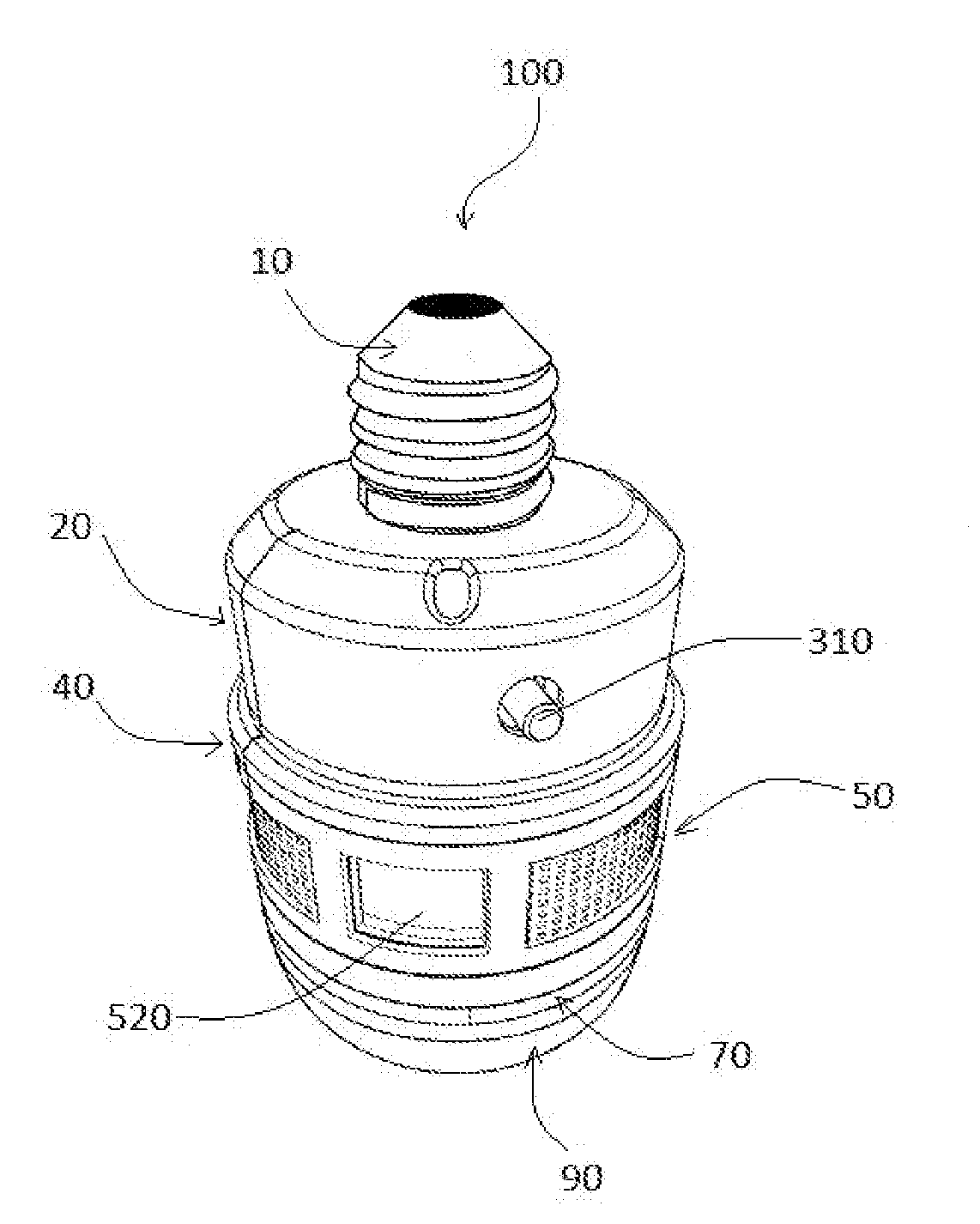
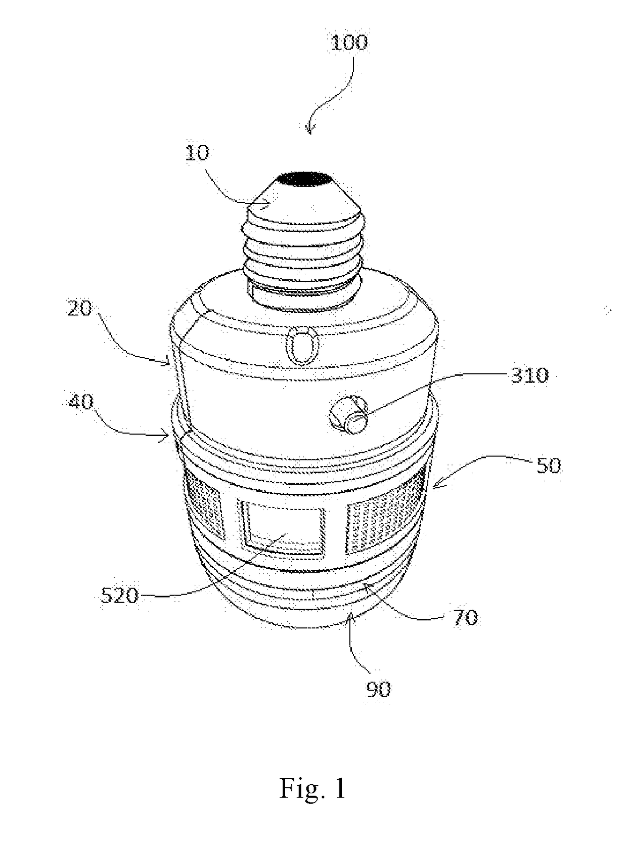
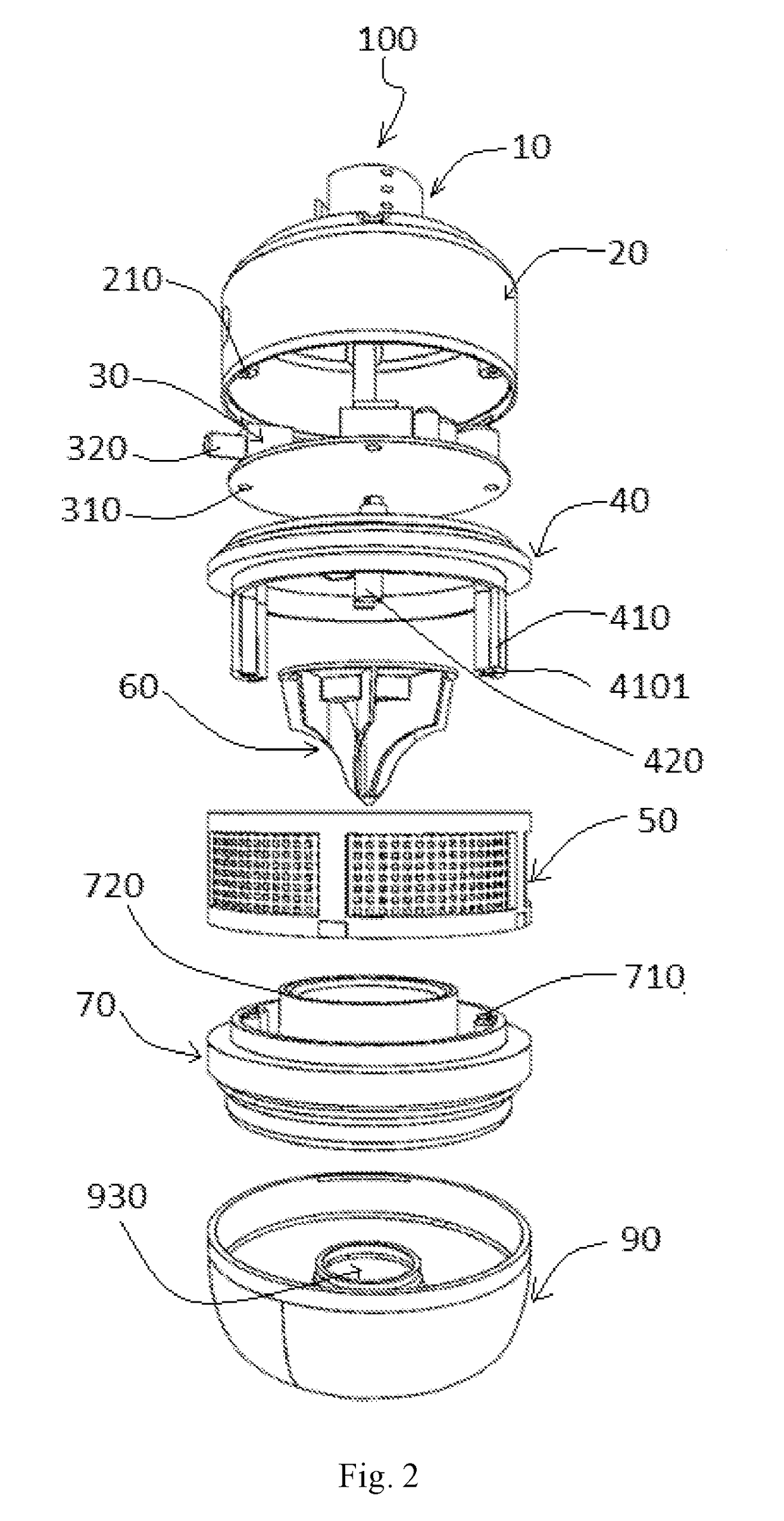
[0025]The present invention will be further described by referring to the accompanying drawings. It should be understood that the embodiments illustrated in the drawings are for description of the invention only and shall not be construed as any limitation to the present invention. The scope of the invention would rather be defined by the appended claims.

[0026]It should be understood that the accompanying drawings are merely used to illustrate the present invention, and not necessarily drawn in scale.

[0027]It should also be understood that the directional terms such as “above”, “under”, “left”, “right”, “front”, “rear”, “bottom”, or “top”, or the like that may be used herein are merely for the ease of describing the present invention, and they should not be construed as limitations to the present invention in any way.

[0028]For brevity, reference numbers are not provided for all the parts, components or features shown in some of the figures. Thus, a cross reference to all of the draw...


PUM


Abstract

A light, in particular, a light having a fly killing function that can be used for lighting and killing flies including at least one LED chip, a fly storage means, a negative pressure fan, a fan hanger, a ventilation net, a power supply; wherein the fly storage means is connected to the fan hanger, the LED chip is secured to an lower end of the fly storage means, the fly storage means including an air inlet and a fly storage groove, the negative pressure fan is mounted onto the fan hanger above the fly storage means, a gap is provided between the blades of the negative pressure fan and an upper end of the fly storage means to allow flies to go through; the ventilation net includes a plurality of ventilation holes having a size that is able to stop flies from passing therethrough, and the ventilation net is provided circumferentially between the outside wall of the fan hanger and the outside wall of the fly storage means, and the fan hanger, the ventilation net and the fly storage means form a substantially closed space except the ventilation holes and the air inlet.

Description

FIELD OF THE INVENTION[0001]The present invention relates to a light. More specifically, the present invention relates to a light having a fly killing function that can be used for both lighting and killing flies.TECHNICAL BACKGROUND OF THE INVENTION[0002]Fly killing lamp is generally an effective black light fly killing device which takes advantage of behaviors of flies, such asphotokinesis, moving with air flow, sensitive to temperature, gregariousness, especially the behavior of chasing carbon dioxide wind and sex pheromone. The fly killing lamp typically does not use any fly killing chemicals, and thus is an environmentally friendly and pollution-free way of killing flies.[0003]Chinese Patent CN 201270731 Y discloses a photocatalysis fly killer comprising a shell having an upper opening, a fan fixed at the upper opening of the shell by a fixing holder, a ventilation filter screen provided at the side surface of the lower section of the shell; a titanium oxide coated plate is fix...

Claims


Application Information

Patent Timeline
IPC IPC(8): A01M1/08A01M1/10F21V23/00F21V19/00F21V3/02F04D19/00F04D29/64F04D29/70
CPCA01M1/08A01M1/106F21V23/001F21V19/005A01M2200/012F04D19/002F04D29/644F04D29/703F21Y2115/10F21V3/02F04D17/16F21V33/00F21K9/232F21Y2103/33F21K9/237Y02A50/30A01M1/06A01M1/10A01M1/00A01M1/04
Inventor ZHANG, JIANCAMERON, ROBERT BRUCE
Owner ZHANG JIAN
Why Eureka
Try Eureka