Water injection device of an internal combustion engine

a technology of internal combustion engine and water injection device, which is applied in the direction of combustion engine, non-fuel substance addition to fuel, charge feed system, etc., can solve the problems of functional impairment, standing water may heat up and possibly evaporate, and the internal combustion engine may not be optimally operated in the operating point with high load respect, so as to avoid a knocking tendency and shorten the build-up time

Active Publication Date: 2018-05-03
ROBERT BOSCH GMBH
View PDF5 Cites 4 Cited by
  • Summary
  • Abstract
  • Description
  • Claims
  • Application Information

AI Technical Summary

Benefits of technology

[0015]The internal combustion engine is in particular preferably operated according to the Otto principle and with gasoline. The internal combustion engine operated according to the Otto principle is to be understood as an internal combustion engine in which gasoline or a gasoline-air mixture is combusted by spark ignition in the form of a spark plug. Since the ignition timing in such an internal combustion engine is precisely predetermined by the spark ignition, the advantages described with respect to the water injection device according to the present invention may be fully utilized. Because of the short pressure build-up times and the rapid injection release of the water injection device according to the present invention, it is also possible to avoid a knocking tendency in the case of rapid, sudden load variations.

Problems solved by technology

However, conventional internal combustion engines may not be optimally operated in operating points having high load with respect to consumption, since the operation is limited due to a knocking tendency and high exhaust gas temperatures.
Because of the high temperatures of the parts of the internal combustion engine close to the water injection system, the standing water may heat up and possibly evaporate.
The formation of vapor may result in functional impairments when restarting the water injection system, since the system pressure may be only slowly built up as a result of the vapor.
This delays the operational readiness of the water injection system.
This delayed operational readiness may result in temperature peaks in the exhaust gas as well as in incidences of knocking in the combustion during sudden load variations.

Method used


Image

  • Water injection device of an internal combustion engine
  • Water injection device of an internal combustion engine
  • Water injection device of an internal combustion engine

Examples


Embodiment Construction

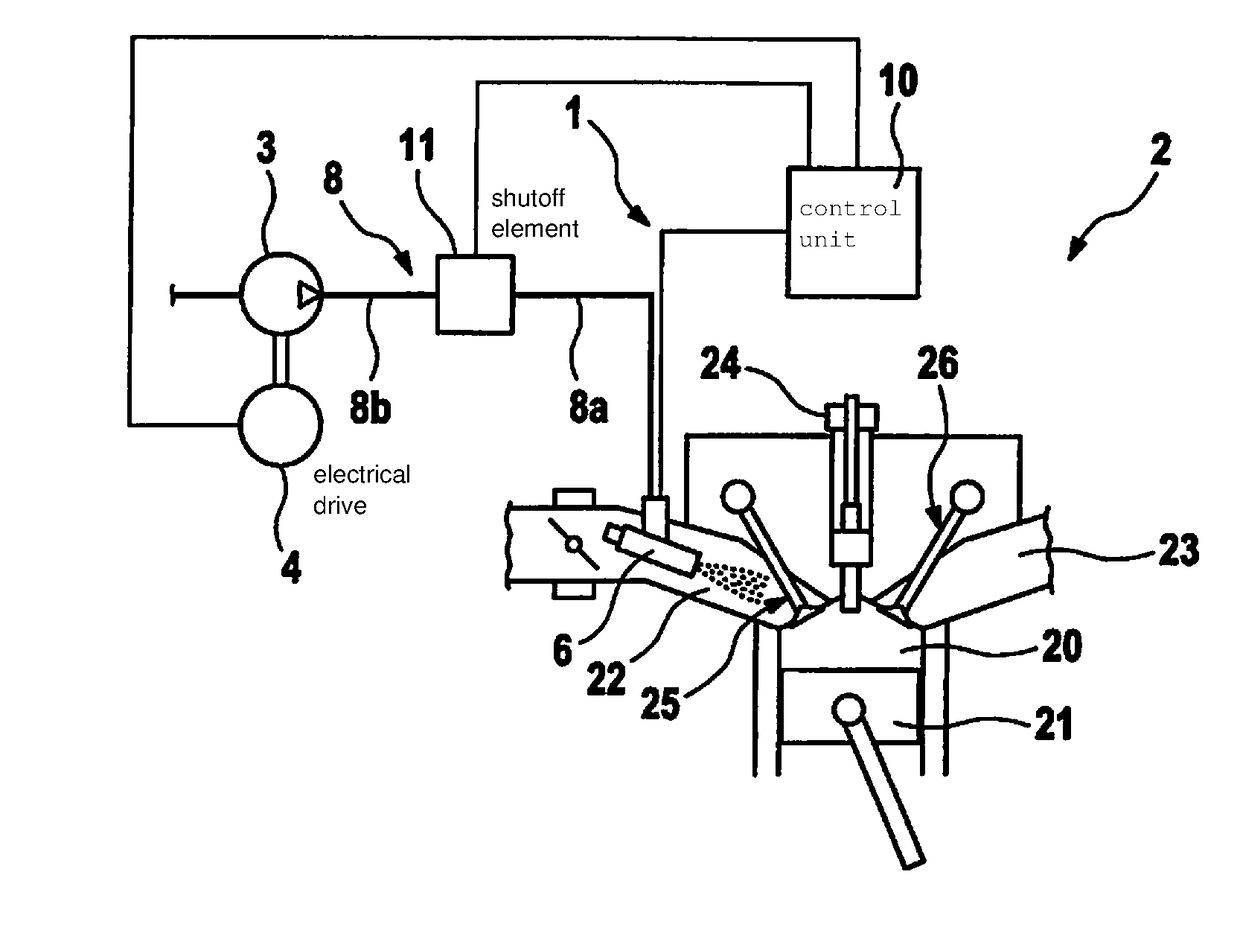
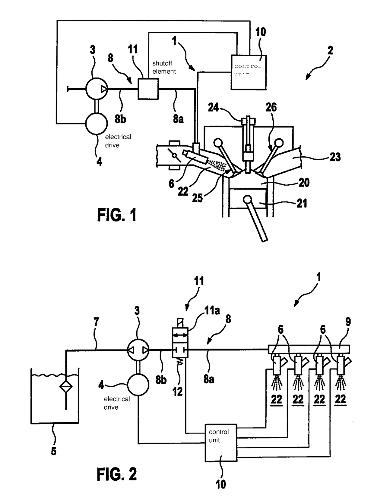
[0020]A water injection device 1 of an internal combustion engine 2 according to a first exemplary embodiment is described in detail below with reference to the FIGS. 1 and 2. Internal combustion engine 2 is operated, in particular, according to the Otto principle and with direct gasoline injection.

[0021]Depicted schematically in FIG. 1 is internal combustion engine 2, which includes a plurality of cylinders, as well as a part of the water injection device 1 according to the present invention. Internal combustion engine 2 includes one combustion chamber 20 per cylinder, in which a piston 21 is movable back and forth. Internal combustion engine 2 also includes one inlet port 22 per cylinder, through which air is fed to combustion chamber 20. Exhaust gas is discharged through an exhaust port 23. For this purpose, an inlet valve 25 is situated at inlet port 22 and an outlet valve 26 is situated at exhaust port 23. Reference numeral 24 also refers to a fuel injector.

[0022]A water inject...


PUM


Abstract

A water injection device of an internal combustion engine, including a water tank for storing water, at least one water injector, a conveying element for conveying water from the water tank into the water injector, and a shut-off element, which is situated in an area between the conveying element and the water injector, and which is configured to maintain a system pressure between the shut-off element and the water injector at a level such that water situated in the area is prevented from evaporating. An internal combustion engine, which includes a water injection device.

Description

FIELD[0001]The present invention relates to a water injection device of an internal combustion engine and to an internal combustion engine of this type.BACKGROUND INFORMATION[0002]Due to increasing demands for reduced carbon dioxide emissions, internal combustion engines are increasingly optimized with respect to fuel consumption. However, conventional internal combustion engines may not be optimally operated in operating points having high load with respect to consumption, since the operation is limited due to a knocking tendency and high exhaust gas temperatures. One potential measure for reducing the knocking tendency and for lowering the exhaust gas temperatures is the injection of water. In this case, separate water injection systems are normally present to enable the injection of water. Thus, for example, a water injection system for an internal combustion engine having an exhaust gas recirculation system is described in PCT App. No. WO 2014 / 080266 A1, in which the water is in...

Claims


Application Information

Patent Timeline
Patent Type & Authority Applications(United States)
IPC IPC(8): F02M25/022F02M25/025
CPCF02M25/0227F02M25/025F02M25/0222F02M25/0221F02M25/028Y02T10/12
Inventor OBERGFAELL, SIMONBURAK, INGMARSCHENK, PETER
Owner ROBERT BOSCH GMBH
Why Eureka
Try Eureka