
Monolithic diffuser plate, and backlight unit and liquid crystal display device using the same

Active Publication Date: 2018-05-03
LG DISPLAY CO LTD
View PDF0 Cites 0 Cited by
  • Summary
  • Abstract
  • Description
  • Claims
  • Application Information

AI Technical Summary

Benefits of technology

The patent describes a special diffuser plate that can withstand changes in temperature and humidity, making it more reliable and efficient. It uses a transparent glass substrate and multiple optical sheets integrated with each other, resulting in improved optical performance and a thinner profile. The diffuser plate also includes a hiding diffusion part, which enhances its ability to hide light sources from view. This technology is useful for creating backlight units and LCD devices.

Problems solved by technology

In such an LCD device, the role and function of the backlight unit are considered to be a more and more important issue.
However, the reduction in size and weight of the backlight unit has degraded the durability and reliability of optical components thereof.
Since the acrylic resin is flexible, a deflection may be caused by the weight of the acrylic resin.
In this instance, the distances between the diffuser plate and the light sources may become uneven, and the diffuser plate may be deformed by heat or melted.
The deflection of the diffuser plate by gravity or the deformation of the diffuser plate by heat or moisture may cause light to be unevenly incident on the liquid crystal panel, and form irregular stains on the screen, thereby degrading the quality of the LCD device.

Method used


Image

  • Monolithic diffuser plate, and backlight unit and liquid crystal display device using the same
  • Monolithic diffuser plate, and backlight unit and liquid crystal display device using the same
  • Monolithic diffuser plate, and backlight unit and liquid crystal display device using the same

Examples


first embodiment

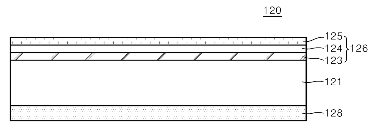
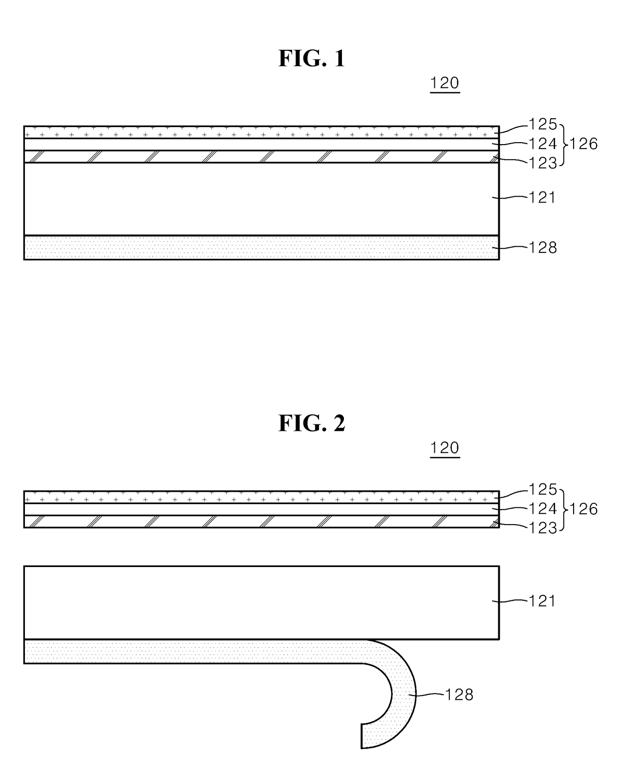
[0025]FIG. 1 is a cross-sectional view of a monolithic diffuser plate according to the present invention. FIG. 2 is a cross-sectional view illustrating components of the monolithic diffuser plate of FIG. 1, depending on a fabrication method.

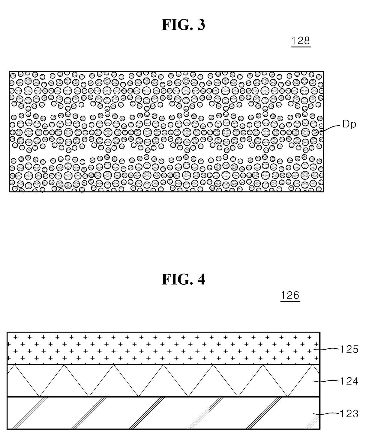
[0026]The diffuser plate 120 illustrated in FIGS. 1 and 2 includes a base substrate 121 made of transparent glass, a diffusion sheet part 126 disposed on the front surface of the base substrate 121, and a hiding diffusion part 128 disposed on the rear surface of the base substrate 121.

[0027]The base substrate 121 can include a transparent low-iron unreinforced glass substrate. When the base substrate 121 is made of transparent unreinforced glass, the base substrate 121 can be more resistant to heat and water than plastics or acrylic resin such as PMMA. Furthermore, although the base substrate 121 is exposed to visual light or ultraviolet light for a long time, the base substrate 121 is not easily changed or warped. Therefore, the lifetime of the ...

second embodiment

[0048]FIG. 6 is a cross-sectional view of a monolithic diffuser plate according to the present invention. FIG. 7 is an exploded cross-sectional view illustrating components of the monolithic diffuser plate of FIG. 6, depending on a fabrication method.

[0049]The monolithic diffuser plate 120 illustrated in FIGS. 6 and 7 has the same structure as the monolithic diffuser plate 120 illustrated in FIG. 1 except for a sheet-type hiding diffusion part 129 formed on the rear surface of the base substrate 121.

[0050]Thus, the descriptions of the structures and technical features of the base substrate 121 and the diffusion sheet part 126 will be replaced by the descriptions of those in the first embodiment and will not be repeated.

[0051]In the second embodiment, the sheet-type hiding diffusion part 129 can further increase the optical diffusion efficiency and the hiding power for hiding the light sources.

[0052]Specifically, the sheet-type hiding diffusion part 129 can be formed through a roll-t...


PUM


Abstract

A monolithic diffuser plate for a backlight unit or a liquid crystal display (LCD) device can include a base substrate made of transparent glass, a monolithic diffusion sheet part integrated on a front surface of the base substrate, and a hiding diffusion part integrated on a rear surface of the base substrate for increasing a hiding power of the base substrate. The monolithic diffuser plate can increase a hiding power for hiding individual light sources in a backlight unit, prevent deformations caused by temperature variations and surrounding environmental factors, and minimize the thickness of a product using the monolithic diffuser plate while also increasing the reliability the product.

Description

CROSS-REFERENCE TO RELATED APPLICATIONS[0001]This application claims the priority of Korean Patent Application No. 10-2016-0141653 filed in the Republic of Korea on Oct. 28, 2016, the disclosure of which is hereby incorporated by reference in its entirety.BACKGROUND OF THE INVENTIONTechnical Field[0002]The present disclosure relates to a monolithic diffuser plate used in a backlight unit and a liquid crystal display (LCD) device, and a monolithic diffuser plate which is capable of further increasing a hiding effect while preventing a deformation caused by a variation in temperature or surrounding environment, thereby minimizing the thickness of products and improving the reliability of the products, and a backlight unit and LCD device using the same.Related Art[0003]An LCD device refers to a device that converts a specific molecular arrangement of liquid crystal into a different molecular arrangement by applying a voltage to the specific molecular arrangement, and converts a change ...

Claims


Application Information

Patent Timeline
IPC IPC(8): G02F1/1335
CPCG02B5/021G02B5/0226G02B5/0231G02F1/133606G02F1/133607G02F1/133611G02B5/0236G02B5/0278G02F2201/54G02F1/133504G02F1/133603G02F1/133308G02B6/0051G02F1/133314G02F1/133507
Inventor PARK, KIDUCKPARK, JONGWANCHUNG, DONGHYUNPARK, JUNSOO
Owner LG DISPLAY CO LTD
Learn More