Method and device for obtaining mura compensation value, and display panel

a compensation value and display panel technology, applied in the field of display technology, can solve the problems of poor image uniformity, difficult process control of the display panel, and non-uniform display about the display panel

Inactive Publication Date: 2018-05-03
BOE TECH GRP CO LTD +1
View PDF4 Cites 11 Cited by
  • Summary
  • Abstract
  • Description
  • Claims
  • Application Information

AI Technical Summary

Benefits of technology

[0002]Embodiments of the present disclosure relate to a field of display technology, and more particularly, to a method for obtaining a mura compensation value, a device for obtaining the mura compensation value, and a display panel.
[0013]an image acquisition and three-primary-colors display data matrix extraction device, configured for obtaining an image of a detection picture displayed on a display panel and extracting display data matrices of three primary colors from the image of the detection picture;
[0089]The compensation is not implemented to all the pixels having deviations of grayscale values, but only to the pixels having deviations greater than a certain threshold, therefore the data amount of the generated compensation data is relatively small, the calculation speed is fast and the algorithm complexity is reduced, while improving the compensation precision.
[0017]a third correction matrix extraction device, configured for extracting a third correction matrix of each primary color from the second correction matrix of the each primary color based on position coordinates of an extreme point of the first correction matrix of the each primary color and forming a third correction matrix group of the primary color from third correction matrices extracted based on the position coordinates of all extreme points of the first correction matrix of the primary color; and

Problems solved by technology

Term “mura” refers to a phenomenon of non-uniform display about a display panel, which is caused by factors of manufacturing process level, raw material purity and so on and is a prevalent technical problem in the field of display technology.
However, process control for the display panel is more and more difficult as the size thereof increases, and control deviation of the manufacturing process is likely to cause a poor image uniformity, thereby generating the mura phenomenon.
Such phenomenon will directly result in a reduced yield of the display panel and in turn make the manufacturers suffer losses.
Although the probability of occurrence of the mura phenomenon can be reduced by improving the process level, improving the raw material purity or the like, it is too difficult to achieve this goal in a short time.
Furthermore, after all the manufacturing processes have been completed, physical properties of the display panel has been determined, it is impossible to solve the mura problem by improving the process level or improving the raw material purity.
The existing way for obtaining the compensation data in the prior art presents disadvantages such as a low compensation precision and a large data processing amount.
Therefore, it is one of the problems needed to be solved in the art how to obtain a method with a high compensation precision and a small data processing amount.

Method used


Image

  • Method and device for obtaining mura compensation value, and display panel
  • Method and device for obtaining mura compensation value, and display panel
  • Method and device for obtaining mura compensation value, and display panel

Examples


first embodiment

[0027]The display panel to which the present disclosure is directed is for example, but not limited to, a plasma display panel, a liquid crystal display panel (LCD), a light emitting diode display panel (LED), or an organic light emitting diode display panel (OLED). The display panel has a resolution of M×N (M and N are positive integers), and each of pixels displays on the basis of display data of RGB three primary colors. The display data are optionally grayscale values of the pixels, luminance values of the pixels, or driving voltage values of the pixels.

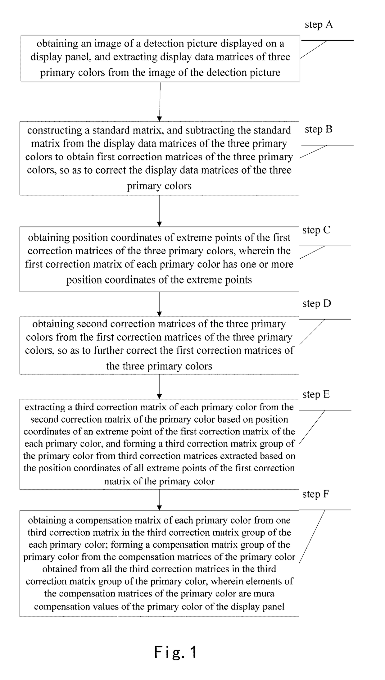
[0028]The step A specifically includes steps of:

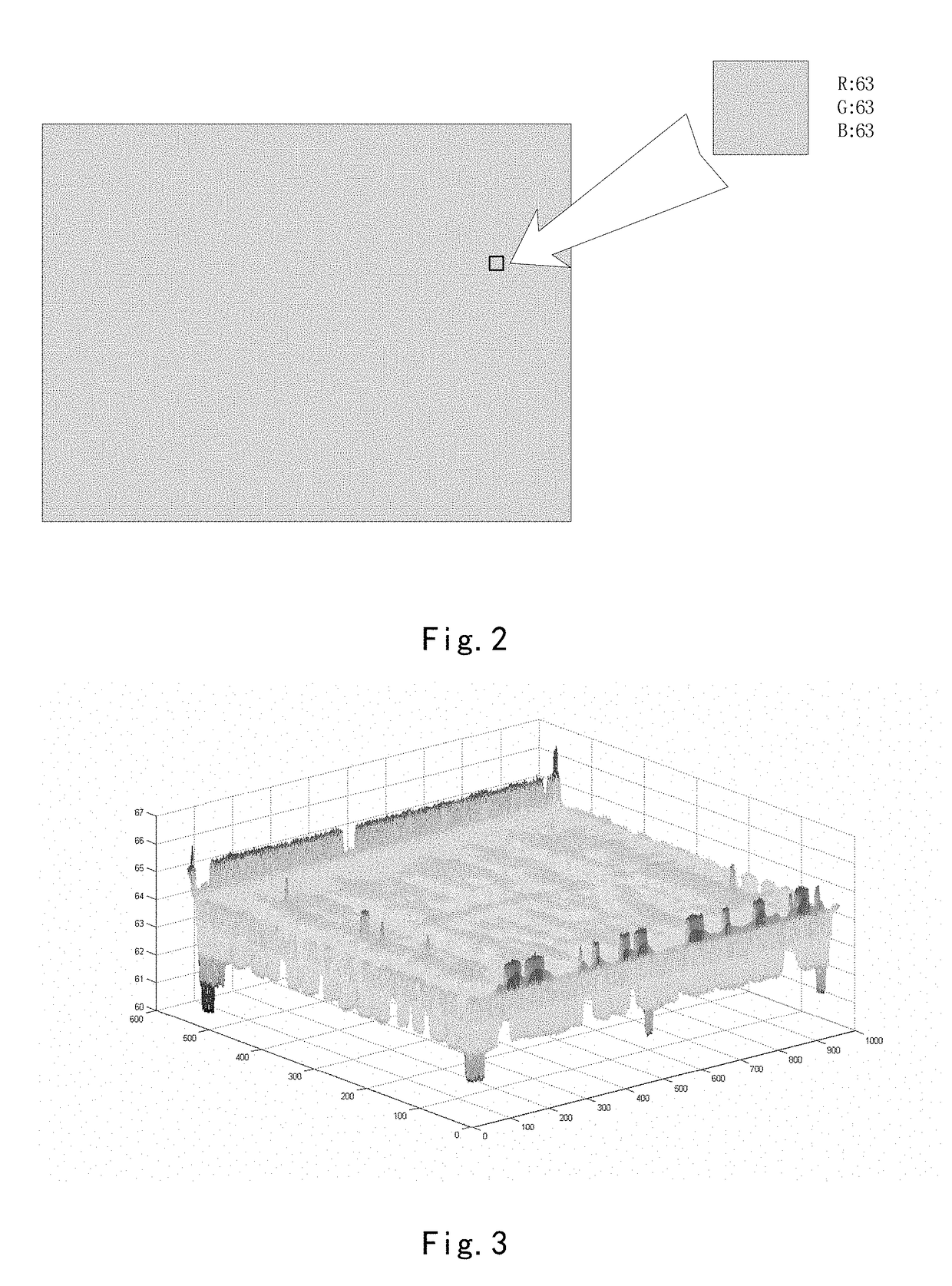
[0029]Sub-step A1: selecting the grayscale values as the display data, and a display panel with a resolution of M×N to display the detection picture, wherein the grayscale values of RGB three primary colors of all the pixels of the detection picture are grayscale values to be set, i.e., the detection picture is a picture of pure color gray scale.

[0030]For example, as shown in FIG. 2...

third embodiment

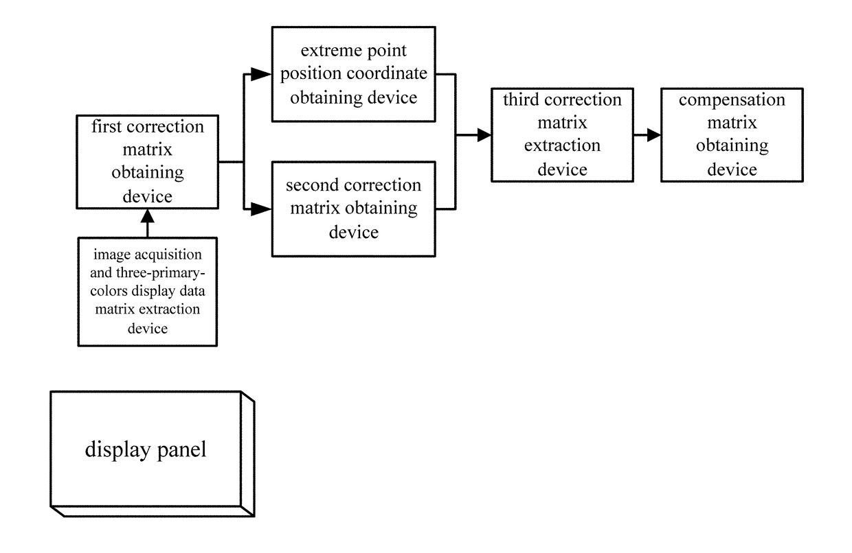
[0086]There is provided a display panel in the present disclosure. The display panel includes a driver and a storage device, wherein the compensation matrix group obtained by the device for obtaining the mura compensation value according to the above embodiments is stored in the storage device, and the driver is configured to perform a mura compensation to the display panel using the compensation matrices in the compensation matrix group.

[0087]In view of the above technical solutions, the method for obtaining a mura compensation value, the device for obtaining a mura compensation value and the display panel in the present disclosure have the following advantageous effects:

[0088]The grayscale values of the RGB three primary colors are extracted from the pixels of the image of the detection picture, and the compensation matrices are respectively generated for the grayscale values of the RGB three primary colors, therefore the compensation mode is finer, and the compensation precision ...


PUM


Abstract

The present disclosure provides a method for obtaining a mura compensation value, a device for obtaining a mura compensation value and a display panel. The method includes: obtaining an image of a detection picture displayed on a display panel, extracting display data matrices of three primary colors, obtaining first correction matrices of the three primary colors, obtaining position coordinates of extreme points of the first correction matrices of the three primary colors, obtaining second correction matrices and a third correction matrix group of the three primary colors, obtaining compensation matrices from the third correction matrices as mura compensation values of the display panel.

Description

CROSS-REFERENCE TO RELATED APPLICATION[0001]This application claims priority of Chinese Patent Application No. 201610206534.9 filed on Apr. 5, 2016, entitled “METHOD AND DEVICE FOR OBTAINING MURA COMPENSATION VALUE, AND DISPLAY PANEL”, in the State Intellectual Property Office of China, the disclosure of which is incorporated in entirety herein by reference.BACKGROUNDTechnical Field[0002]Embodiments of the present disclosure relate to a field of display technology, and more particularly, to a method for obtaining a mura compensation value, a device for obtaining the mura compensation value, and a display panel.Description of the Related Art[0003]Term “mura” refers to a phenomenon of non-uniform display about a display panel, which is caused by factors of manufacturing process level, raw material purity and so on and is a prevalent technical problem in the field of display technology. As video display technology rapidly develops, a display technique being large-sized, having ultra-hi...

Claims


Application Information

Patent Timeline
Patent Type & Authority Applications(United States)
IPC IPC(8): G09G3/20
CPCG09G3/2003G09G3/2088G09G2320/0242G09G2320/0276G09G2320/0285G09G2320/0693
Inventor HE, ZONGZEWANG, JIEQIONGSU, DANLI, SHUOYANG, JIANGUANGFENG, ZHIPENGZHANG, LIANG
Owner BOE TECH GRP CO LTD
Why Eureka
Try Eureka