
Screw driving device for use with an impact driver

Active Publication Date: 2018-05-10
RAJOTTE JACQUES
View PDF13 Cites 4 Cited by
  • Summary
  • Abstract
  • Description
  • Claims
  • Application Information

AI Technical Summary

Benefits of technology

The invention is a screw driving device for an impact driver that allows for easy and secure use of screw bits. The device includes a drive shaft with a clutch bearing that engages the screw bit in the drive position and disengages in the clutched position, a hollow clutch sleeve with a central passage that receives the drive shaft and has annular grooves to hold the clutch bearing, a depth control sleeve that surrounds the hollow clutch sleeve, and a spring to push the drive shaft towards the drive position. The device also includes a drive shaft with a drive end adapted to be engaged and driven by the impact driver and a socket end with an annular wall that forms a socket that receives and retains a screw bit, the annular wall having a plurality of radial bores that receive the clutch bearing in the drive position and disengage in the clutched position to allow for rotation of the screw bit. The device provides a simple and effective solution for driving screws with an impact driver.

Problems solved by technology

However, longer and longer screws are now being used in the construction industry, and electric drills are not efficient at driving those screws.
However, observation has how shown that the concussive effect of driving screws with the impact driver can cause the round bearings of a screw driving device to spall the edges of a shank of a screw driving bit they retain in a drive position.
Consequently, the screw driving bit has to be replaced before the screw driving tip of the bit has reached the limit of its service life.
This is an undesirable situation.

Method used


Image

  • Screw driving device for use with an impact driver
  • Screw driving device for use with an impact driver
  • Screw driving device for use with an impact driver

Examples


Embodiment Construction

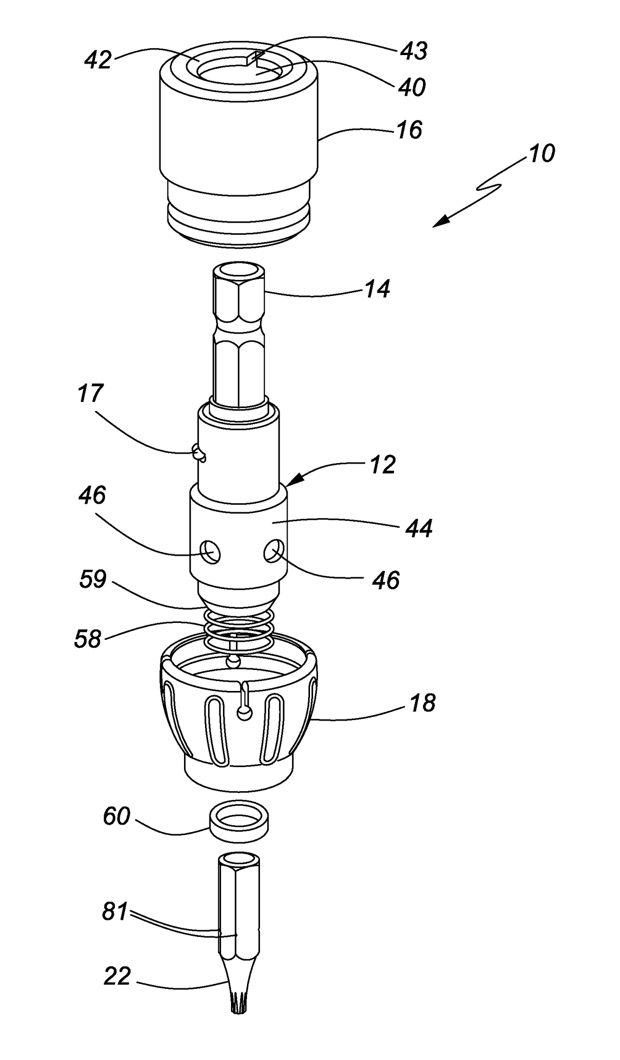
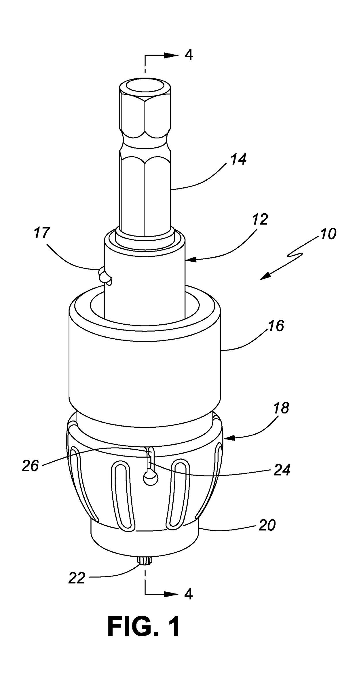
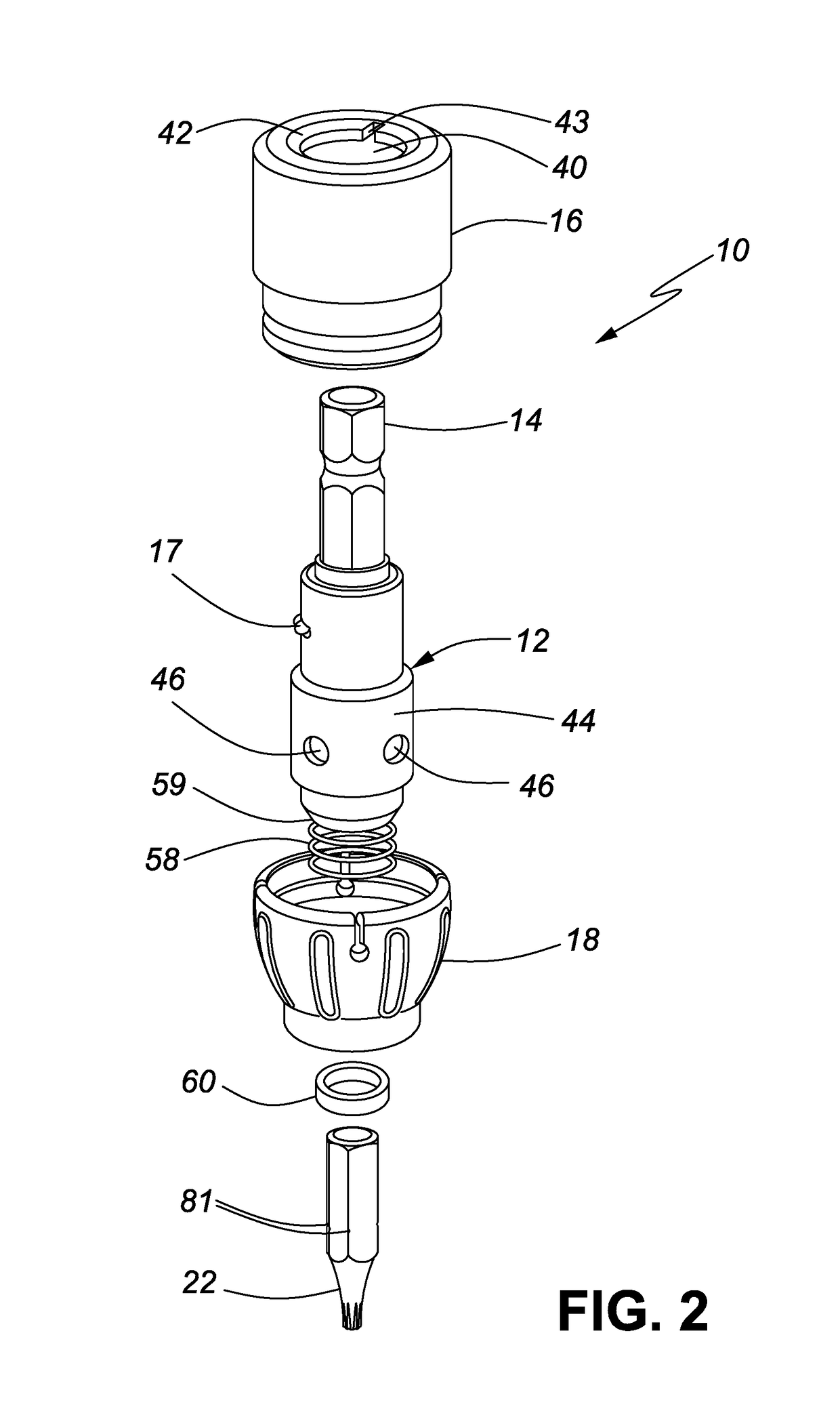
[0019]FIG. 1 is a perspective view of a screw driving device 10 in accordance with the invention. The screw driving device 10 has a drive shaft 12 with a drive end 14 adapted to be engaged and driven by a portable electric impact driver (not shown), a hand tool that is well known in the art. A hollow clutch sleeve 16 receives the drive shaft 12. A lock boss 17 is formed on a side of the drive shaft 12 to lock the screw driving device 10 in a locked position for removing driven screws, as will be explained below with reference to FIG. 9. A nose cone 18 grips a bottom end of the hollow clutch sleeve 16, the nose cone 18 has a bottom end 20 through which extends a screw bit 22 received in a bottom end of the drive shaft 12. As will be explained below with reference to FIGS. 4-8, the screw bit 22 rotates with the drive shaft 12 when the screw driving device 10 is in a drive position and is released from driving engagement with the drive shaft 12 when the screw driving device 10 is in a ...


PUM


Abstract

A screw driving device for an impact driver has cylindrical clutch bearings with frusta-conical inner ends that contact a screw bit retained by the screw driving device to drive a screw to a predetermined depth in a work piece and release the screw bit in a clutched position that is achieved when the screw has been driven to the predetermined depth in the work piece.

Description

FIELD OF THE INVENTION[0001]The present invention relates to a screw driving device and, in particular, a screw driving device to control the depth at which a screw is driven into a work piece using an impact driver.BACKGROUND OF THE INVENTION[0002]Existing devices for driving screws using a power tool, such as an electric drill or an impact driver, are well known in the art, as characterized by Applicant's U.S. Pat. No. 9,302,377 B2, which issued on Apr. 4, 2016.[0003]Such devices work extremely well when driven using an electric drill which provides a smooth, continuous drive force. However, longer and longer screws are now being used in the construction industry, and electric drills are not efficient at driving those screws. Consequently, impact drivers equipped with screw driving devices are being used to drive the long construction screws. The impact drivers provide the concussive torque required to drive the long construction screws while the screw driving devices control scre...

Claims


Application Information

Patent Timeline
IPC IPC(8): B25B23/00B25B23/12B25B21/02
CPCB25B23/0064B25B23/12B25B23/0035B25B21/02
Inventor RAJOTTE, JACQUESWU, KUN-LI
Owner RAJOTTE JACQUES
Learn More