Lining Panel And Method For Manufacturing Lining Panel

a technology of lining panel and manufacturing method, which is applied in the field of lining panel and to a manufacturing method of lining panel, can solve the problems of rapid decompression door interference of noise, uncontrolled decompression, and acoustic gaps within the rapid decompression door, so as to prevent the opening of the flap, maintain the diameter or cross-section of the duct, and ensure the effect of air tightness

Inactive Publication Date: 2018-05-10
AIRBUS OPERATIONS GMBH
View PDF5 Cites 8 Cited by
  • Summary
  • Abstract
  • Description
  • Claims
  • Application Information

AI Technical Summary

Benefits of technology

[0025]The front side may be the side of the panel which faces in an installed mode of the lining element the inside of a passenger cabin of a means of transportation. This side facing the area where passengers are moving around is endangered to be contacted by a passenger. In order to provide a robust surface at least a part of the panel element is covered by a thin layer. The thin layer, the protection cover or the protection layer may be made of a non-reinforced thermoplastic polymer. The protection layer together with the panel element may form a sandwich structure of different sized layers and of different materials The thin layer may have a thickness of equal or below 0.5 mm. The protection layer may be built on the panel element when the panel element itself is built. The protection layer may also prevent opening of the flaps by external force executed by passengers unintentionally contacting the lining panel.
[0026]In addition to the non-reinforced thermoplastic layer in order to provide for further protection, a part of the panel element may be made of a reinforced profile. Such an element may be made from a material other than the panel element and / or the salient. This reinforcement profile may help to maintain the diameter or cross-section of a duct of an airflow and / or may protect a duct from external force. The cross-section may be maintained by a combination of the reinforcement profile, a U-profile and a floor angle. The reinforcement profile provided on the front side can provide additional robustness to prevent deformation of the surface of the panel element by touching the surface. The reinforcement profile may replace a portion of the panel element and may also be covered by the thin protection layer. The reinforcement profile may be integrated into the panel element at the same time when the panel element itself is built. In an example, the reinforcement profile has the same thickness as the panel element, e.g. 10 mm. In another example the reinforcement profile is thicker than the panel element. In yet another example the panel element and the reinforcement profile may form a sandwich. The reinforced profile may also prevent opening of the flaps by external force executed by passengers unintentionally contacting the lining panel.

Problems solved by technology

In the event of any damage the pressure between different areas of the cabin can reach a limit so that uncontrolled decompression can appear by damaging any separating barrier that cannot sustain the pressure difference.
However, these decompression doors comprise several parts leading to acoustical gaps within the rapid decompression doors after being assembled.
As a result of using several parts for building a cabin lining element having a rapid decompression door interferences of noise may arise during the flight.

Method used


Image

  • Lining Panel And Method For Manufacturing Lining Panel
  • Lining Panel And Method For Manufacturing Lining Panel
  • Lining Panel And Method For Manufacturing Lining Panel

Examples


Embodiment Construction

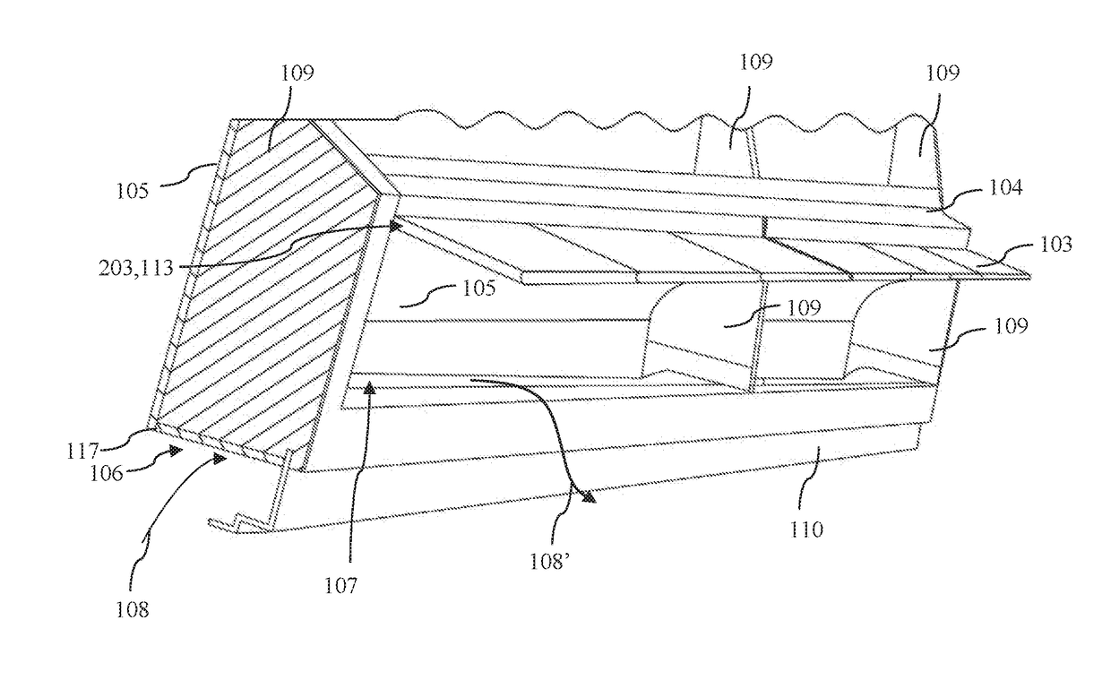
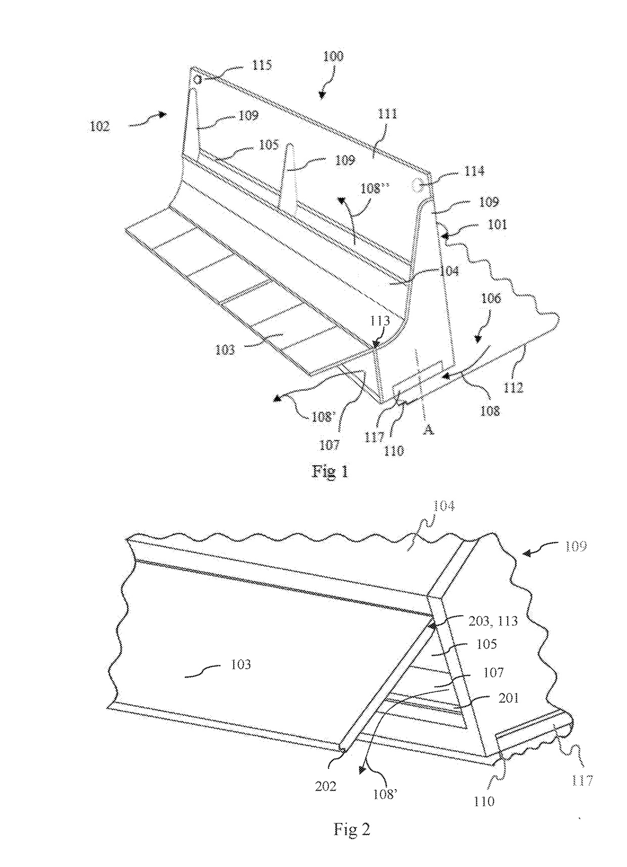
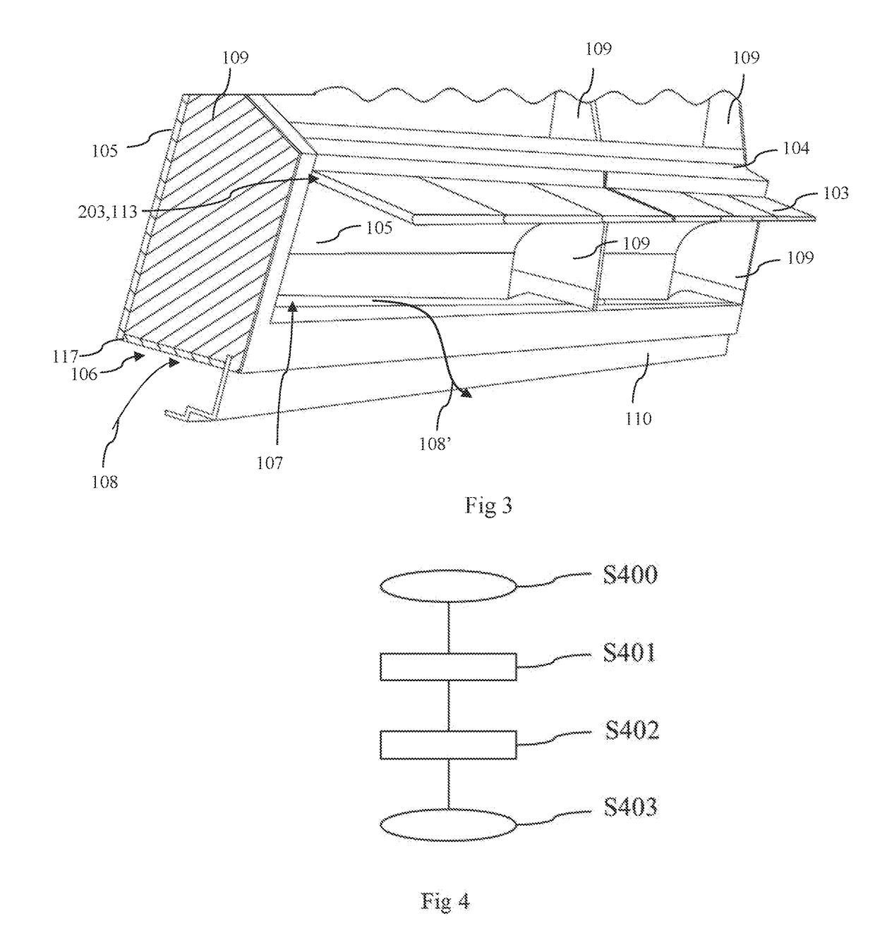
[0046]The illustration in the drawing is schematic and may not to scale. In different drawings similar or identical elements are marked with the same reference numerals.

[0047]FIG. 1 shows the fuselage element 100 or lining panel 100 according to an exemplary embodiment of the present invention. The lining panel 100 comprises panel element 111 having a front side 101 and a back side 102. The terms “front side”101 and “back side”102 may be primarily seen as names in order to differentiate two sides of the panel element 111 but are not intended to be used as a restriction. The front side usually is a name for a side facing an interior area of a cabin. In this interior area, usually passengers are situated or located. The back side 102 of the panel is a name for a side which faces an outside of the fuselage. On the back side, infrastructure of the means of transport can be located. For example, tubes and isolation material are mounted on the back side of the lining panel 100. The backsi...


PUM


Abstract

A lining panel having a panel element, a rectangular through hole and a flap is provided. The lining panel has a flap which is rotatable about a hinge integrated into the panel element in order to open and/or close the rectangular through hole. A fuselage element for an aircraft includes such a lining panel.

Description

FIELD OF THE INVENTION[0001]The present invention relates to the technical field of aerospace engineering. In particular, the present invention relates to a lining panel and to a method for manufacturing a lining panel.BACKGROUND OF THE INVENTION[0002]Aircrafts are pressurized in order to compensate pressure differences during all level of flight and to generate a comfortable and safe environment for passengers inside a pressurized cabin. When pressurized airplane flying at a high altitude, the pressure outside the airplane is considerable lower than inside. As a result of pressurizing the airplane a pressure difference may even occur inside the aircraft between different compartments of the airplane such as a passenger compartment and a cargo compartment.[0003]In the event of any damage the pressure between different areas of the cabin can reach a limit so that uncontrolled decompression can appear by damaging any separating barrier that cannot sustain the pressure difference. For ...

Claims


Application Information

Patent Timeline
Patent Type & Authority Applications(United States)
IPC IPC(8): B64D13/04B64C1/18
CPCB64D13/04B64C1/18B64C2001/009B64C1/066Y02T50/40
Inventor ROTH, INGO
Owner AIRBUS OPERATIONS GMBH
Why Eureka
Try Eureka