
LED highlight decorative bulb

Active Publication Date: 2018-05-10
DONGGUAN CITY MINLEON ELECTRONICS CO LTD
View PDF2 Cites 8 Cited by
  • Summary
  • Abstract
  • Description
  • Claims
  • Application Information

AI Technical Summary

Benefits of technology

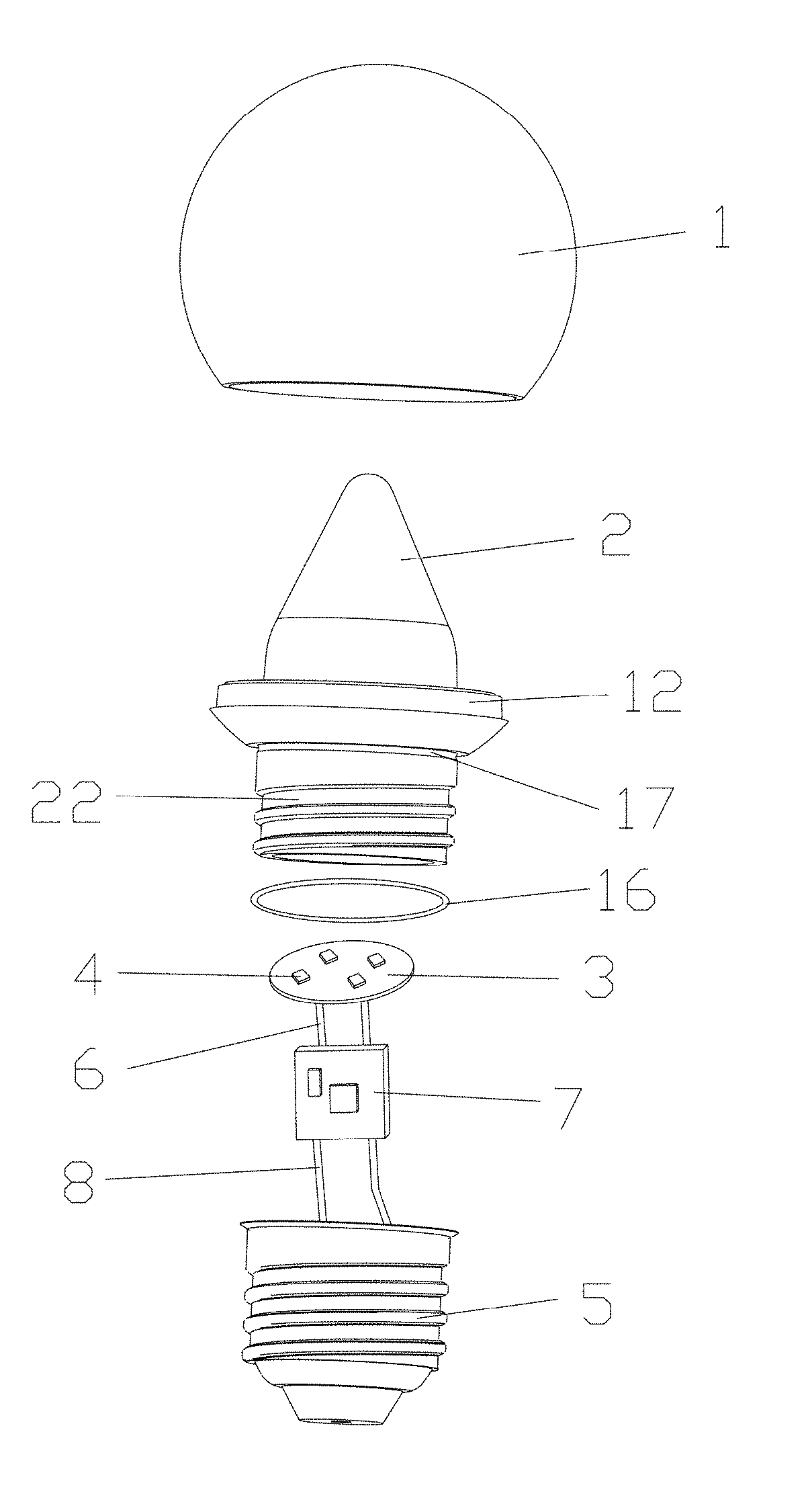
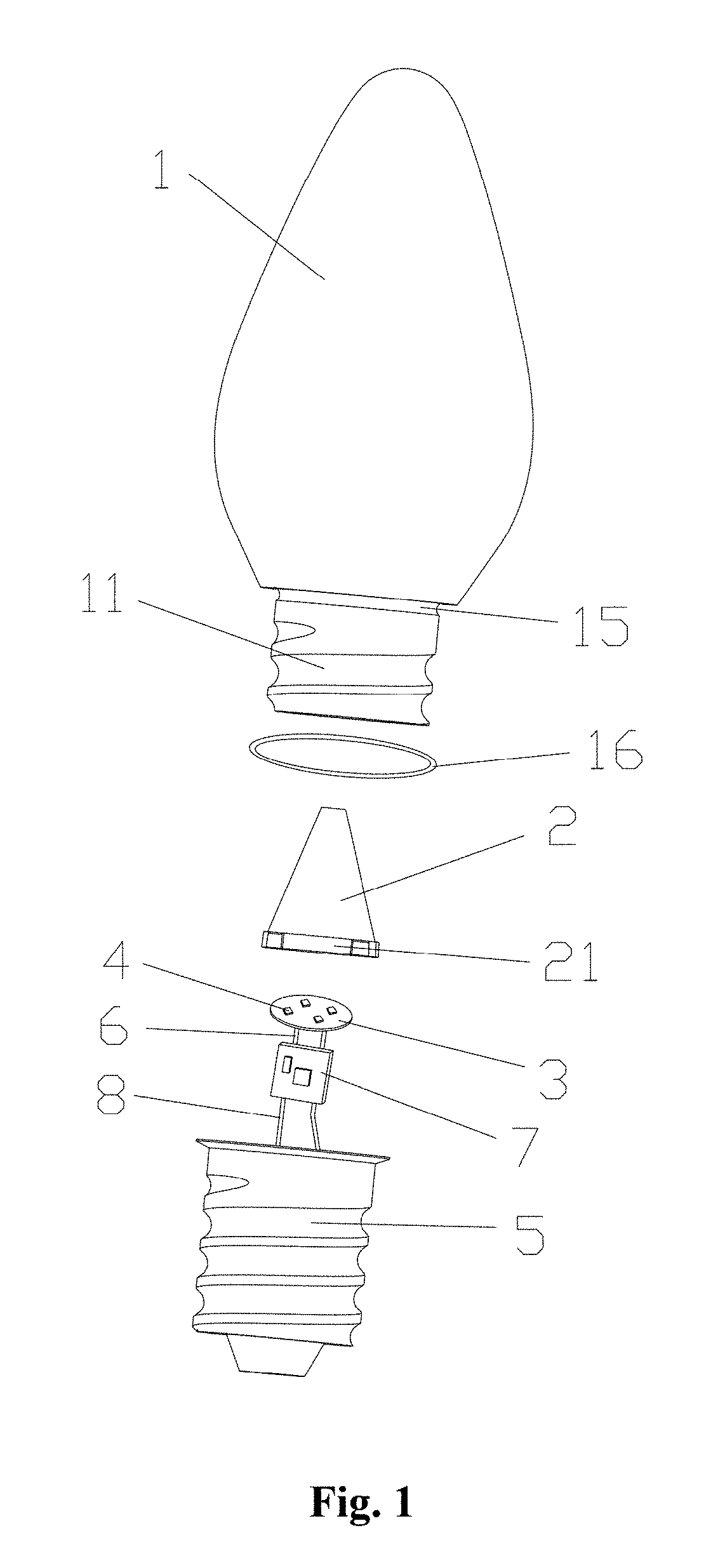
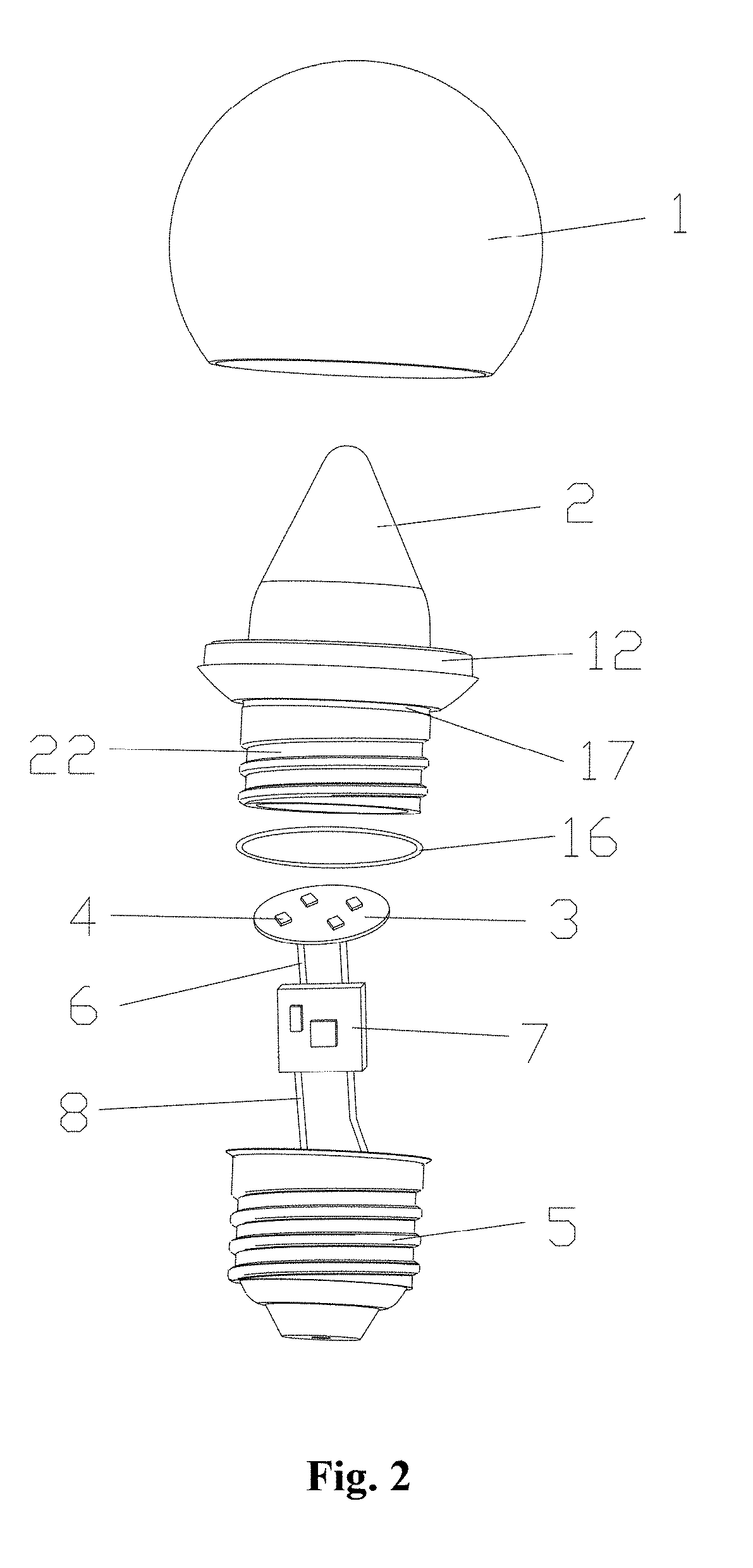
The LED highlight decorative bulb has a better light extracting effect with a higher mixed and scattered light extracting rate, more uniform light extracting, higher light lumen, and higher brightness. It includes a lamp shade capable of being mutually assembled by splicing, a light guide column located in the lamp shade, a flat circuit board arranged in a bottom of the light guide column, a patch LED lighting object arranged in the flat circuit board, and a bulb connecting seat arranged in the bottom of the light guide column. The upper portion of the light guide column is in a shape of solid cone, which helps to mix and scatter the light emitted by the patch LED lighting object. Overall, this results in a more extravagant and complete lighting experience.

Problems solved by technology

In this way, the light emitted from the LED lighting object is not mixed and scattered, so that the emitting quantity of the light will be limited, and the light uniformity is not very good.
However, with respect to the spherical LED bulb through the flat light guide plate, the mixed and scattered light extracting rate is still limited, so as not to light out of the bulb well.

Method used


Image

  • LED highlight decorative bulb
  • LED highlight decorative bulb
  • LED highlight decorative bulb

Examples


first embodiment

[0017]the invention refers to FIG. 1. The bottom of the light guide column is equipped with a fixed ring 21, the bottom of the lamp shade is equipped with an external thread 11, an engagement portion of an upward side of the external thread and the lamp shade is equipped with a lamp shade waterproof groove 15; a waterproof rubber gasket 16 is arranged in the lamp shade waterproof groove, the bulb connecting seat is threaded with the external thread of the bottom of the lamp shade, and the fixed ring 21 of the light guide column is clamped and tightened between the bulb connecting seat and the bottom of the lamp shade. Such structure may make the lower portion structure of the light guide column smaller to save material, and is applicable to a structure of a small-sized bulb. After assembly in this embodiment, the bulb connecting seat presses against the waterproof rubber gasket 16 and the lamp shade waterproof groove 15 in the engagement portion of the lamp shade, so as to achieve a...

second embodiment

[0018]the invention refers to FIG. 2, the bottom of the light guide column is equipped with an external thread connecting seat 22, the external thread connecting seat is equipped with an adhesion fixed station 12 for connecting with the lamp shade, an engagement portion of the external thread connecting seat and the adhesion fixed station is equipped with a fixed station waterproof groove 17, the fixed station waterproof groove is internally equipped with the waterproof rubber ring 16, the lamp shade is fixedly connected with the adhesion fixed station through mucilage glue, and the external thread connecting seat is threaded with the bulb connecting seat. Such structural light guide column may be combined with the lamp shades in different shapes. The assembly may be convenient, so that the cost is saved. After assembly in this embodiment, the bulb connecting seat presses against the waterproof rubber gasket 16 and the fixed station waterproof groove 15 in the engagement portion of ...


PUM


Abstract

The invention discloses an LED highlight decorative bulb, comprising a lamp shade capable of being mutually assembled by splicing, a light guide column located in the lamp shade, a flat circuit board arranged in a bottom of the light guide column, a patch LED lighting object arranged in the flat circuit board, and a bulb connecting seat arranged in the bottom of the light guide column, wherein an upper portion of the light guide column is in a shape of solid cone, a bottom surface of the flat circuit board is electrically connected with a conductive pin, the conductive pin is electrically connected with a vertical circuit board, the vertical circuit board is electrically connected with two electrodes in an inner wall of the bulb connecting seat through a guide line respectively, and the vertical circuit board is electrically connected with an LED driver chip and a resistor element.

Description

FIELD OF THE INVENTION[0001]The invention relates to an illuminating device, and more particularly, to an LED highlight decorative bulb.BACKGROUND OF THE INVENTION[0002]For most of the existing LED bulbs, an LED lighting object is directly installed in a lamp shade, the light from the LED lighting object is directly emitted to the lamp shade, and then lights outwards. In this way, the light emitted from the LED lighting object is not mixed and scattered, so that the emitting quantity of the light will be limited, and the light uniformity is not very good. For the rest of the LED bulb, a flat light guide plate is arranged at the top of the LED lighting object for scattering the light. However, with respect to the spherical LED bulb through the flat light guide plate, the mixed and scattered light extracting rate is still limited, so as not to light out of the bulb well. Therefore, it is necessary to develop a new LED highlight decorative bulb to overcome these above deficiencies.SUMM...

Claims


Application Information

Patent Timeline
IPC IPC(8): F21V3/00F21V31/00F21V17/16F21V17/12F21K9/232F21K9/238F21K9/237F21V8/00
CPCF21V3/00F21V31/005F21V17/16F21V17/12F21Y2115/10F21K9/238F21K9/237G02B6/0001F21K9/232F21V23/006F21K9/61F21Y2105/18F21V3/02F21V19/003F21W2121/00F21K9/235
Inventor CHEN, DONGCHANG
Owner DONGGUAN CITY MINLEON ELECTRONICS CO LTD
Learn More