
Supplemental cooling system load control using random start of first defrost cycle

a cooling system and random start technology, applied in the field of cooling systems, can solve the problems of premature failure, complex process, and rapid increase in compressor pressure ratio and compressor outlet temperature,

Active Publication Date: 2018-05-10
HONEYWELL INT INC
View PDF5 Cites 0 Cited by
  • Summary
  • Abstract
  • Description
  • Claims
  • Application Information

AI Technical Summary

Benefits of technology

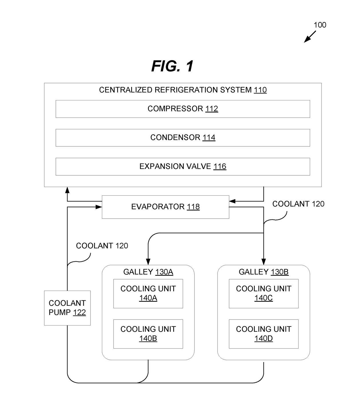
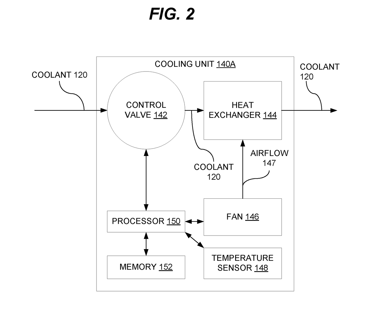
The present invention relates to a method and system for controlling the load of multiple cooling units. The system includes a centralized refrigeration system that provides a shared flow of coolant to multiple cooling units. Each cooling unit allows the flow of coolant to pass through it and has the ability to determine when to initiate a defrost cycle. The system can also deny the flow of coolant during specific defrost cycles to optimize energy usage. The technical effect of this invention is more efficient and precise control of cooling units, leading to improved energy usage and reduced costs.

Problems solved by technology

However, if there is no coordination between the cooling units, then all of the cooling units may enter a periodic defrost cycle at approximately the same time.
When all of the cooling units simultaneously stop the flow of coolant, the lack of coolant flow and heat load causes a rapid drop in the evaporating pressure of the vapor cycle system, which in turn causes a rapid increase in compressor pressure ratio and compressor outlet temperature.
This repeated startup and shutdown cycle causes thermal stress and mechanical stress (wear and tear) on system equipment that can cause premature failure.
Moreover, orchestrating this startup and shutdown cycle is a delicate and challenging process when conducted in the extremely hot or cold environment of an aircraft on ground or in flight.
However, this approach is undesirable in the context of food storage, as food may be kept at unsafe temperatures when cooling units are not powered on right away.
Furthermore, the prior approach may require modifying the software logic and wiring in the refrigeration system.
This software modification may not be feasible, particularly when using an existing turnkey solution.
The additional system software complexity may also make integration, maintenance and repair more difficult, which is particularly troublesome in a commercial aircraft where every minute of downtime counts.

Method used


Image

  • Supplemental cooling system load control using random start of first defrost cycle
  • Supplemental cooling system load control using random start of first defrost cycle
  • Supplemental cooling system load control using random start of first defrost cycle

Examples


Embodiment Construction

[0016]The following detailed description is of the best currently contemplated modes of carrying out exemplary embodiments of the invention.

[0017]The description is not to be taken in a limiting sense, but is made merely for the purpose of illustrating the general principles of the invention, since the scope of the invention is best defined by the appended claims.

[0018]Various inventive features are described below that can each be used independently of one another or in combination with other features.

[0019]Broadly, this invention relates to providing load control for cooling systems. In this invention, each cooling unit in a cooling system may be configured to start a first defrost cycle at a random time within a predetermined time range after the cooling unit is started or powered on. After the first random start defrost cycle, a regular periodic defrost cycle may be maintained. In this manner, all of the cooling units can be turned on at the same time while providing desynchroni...


PUM


Abstract

Methods, apparatus, and systems for load control for cooling systems are provided. Coolant flows through a plurality of cooling units in a cooling system. The coolant flow is halted for each cooling unit that is undergoing a defrost cycle. Each cooling unit is configured to start a first defrost cycle at a random time within a predetermined time range after the cooling unit is started or powered on. After the first random start defrost cycle, a regular periodic defrost cycle may be maintained. Thus, the cooling units may be powered on simultaneously while still providing desynchronized defrost cycles, enabling the cooling system to maintain adequate coolant flow and heat load to avoid deleterious stop and restart cycles.

Description

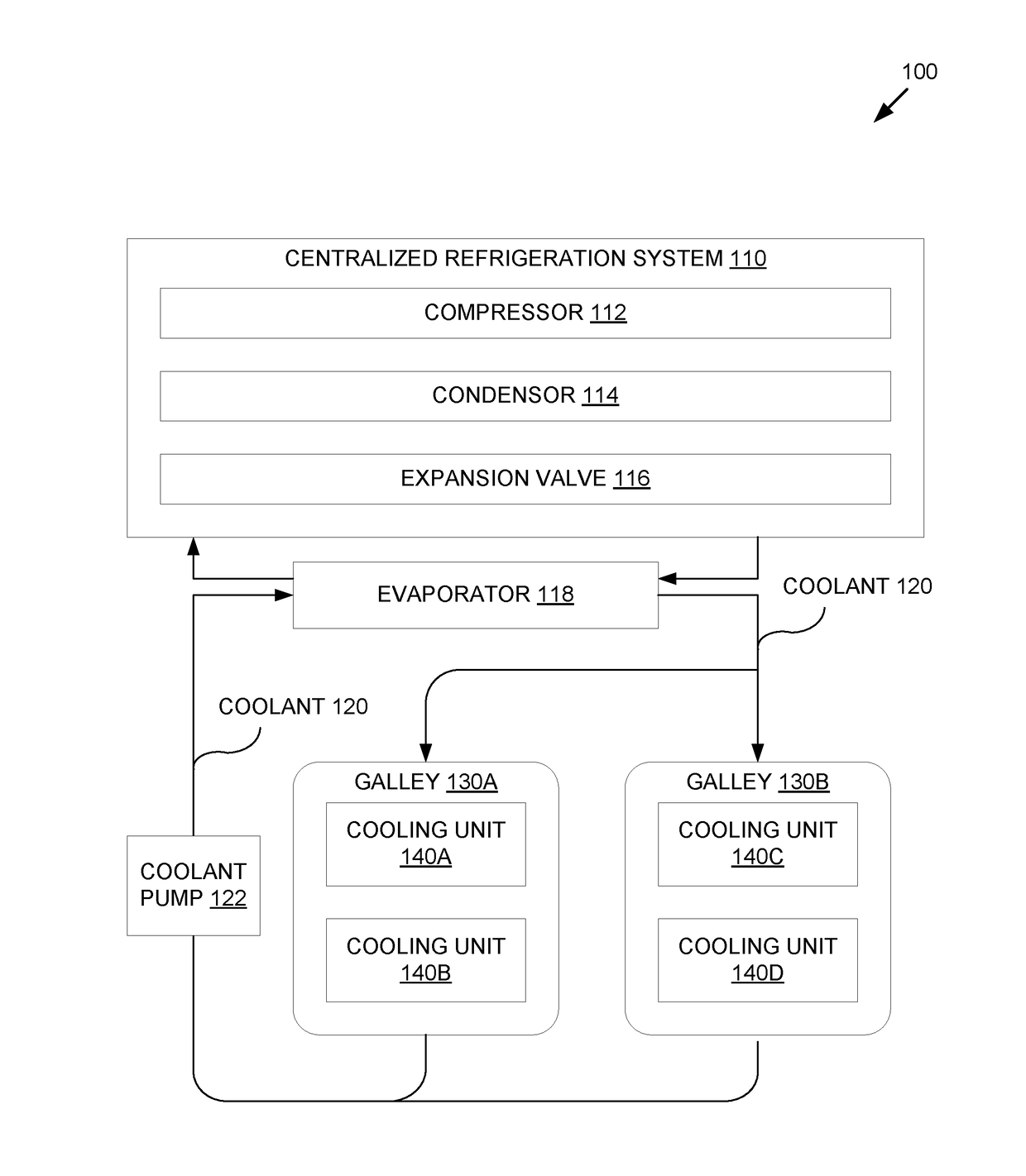
BACKGROUND OF THE INVENTION[0001]The present invention generally relates to cooling systems. More particularly, the present invention relates to apparatus, systems and methods for providing cooling system load control using a random start of a first defrost cycle.[0002]For certain applications, a centralized refrigeration system may be suitable to service multiple locations requiring temperature regulation. One such application is galley cooling on a large commercial aircraft. In this application, a vapor cycle system comprising of a compressor, condenser, expansion valve, evaporator, and refrigerant is often utilized to chill liquid coolant, which is cooled through a centralized evaporator for distribution to various cooling units in the galleys of the aircraft. This coolant may flow through heat exchangers in the cooling units. By using a fan or air convection, the heat exchanger may absorb heat inside the cooling units, thereby reducing the inside ambient temperature to a desired...

Claims


Application Information

Patent Timeline
Patent Type & Authority Applications(United States)
IPC IPC(8): F25D21/06F25D21/00F25D31/00B64D11/00
CPCF25D21/06F25D21/008F25D2331/806B64D11/0007F25D31/006B64D11/04F25D21/006
Inventor TANG, BENJAMINBRUNTER, RANDYZHENG, PETER
Owner HONEYWELL INT INC
Learn More