Radio wave sensor and luminaire

a technology of radio wave sensor and luminaire, which is applied in the direction of instruments, instruments, measurement devices, etc., can solve the problem of increasing the number of components

Inactive Publication Date: 2018-05-10
PANASONIC INTELLECTUAL PROPERTY MANAGEMENT CO LTD
View PDF0 Cites 2 Cited by
  • Summary
  • Abstract
  • Description
  • Claims
  • Application Information

AI Technical Summary

Benefits of technology

[0006]The present disclosure has been achieved in view of the above circumstances, and an object thereof is to provide a radio wave sensor and a luminaire, capable of controlling the directivity of a transmitting antenna without increasing the number of components.

Problems solved by technology

The high frequency sensor (radio wave sensor) described in Document 1 needs a dedicated dielectric lens in order to control the directivity of the transmitting antenna, which causes an increase in the number of components thereof.

Method used


Image

  • Radio wave sensor and luminaire
  • Radio wave sensor and luminaire
  • Radio wave sensor and luminaire

Examples


Embodiment Construction

[0017]Hereinafter, an embodiment of the present disclosure will be explained. Various modifications may be made in the following embodiment as long as the object of the present disclosure can be attained.

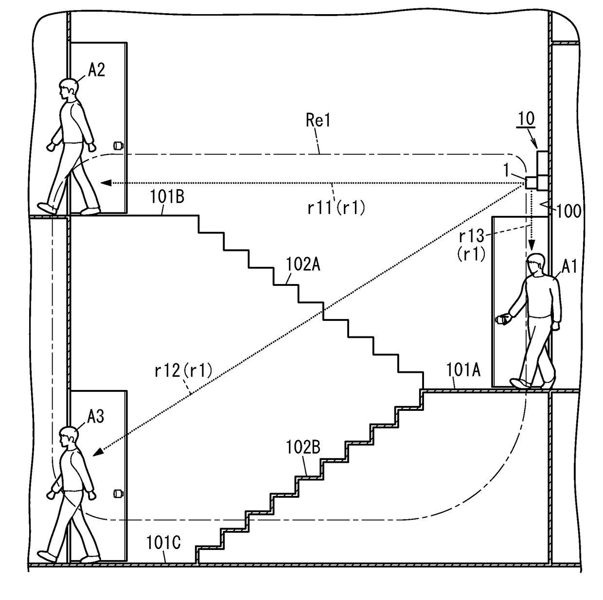
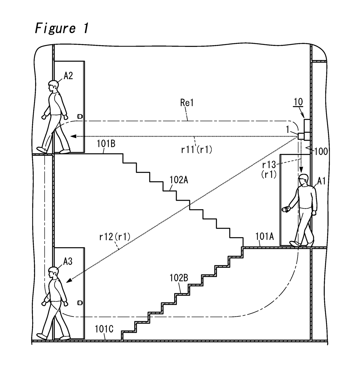
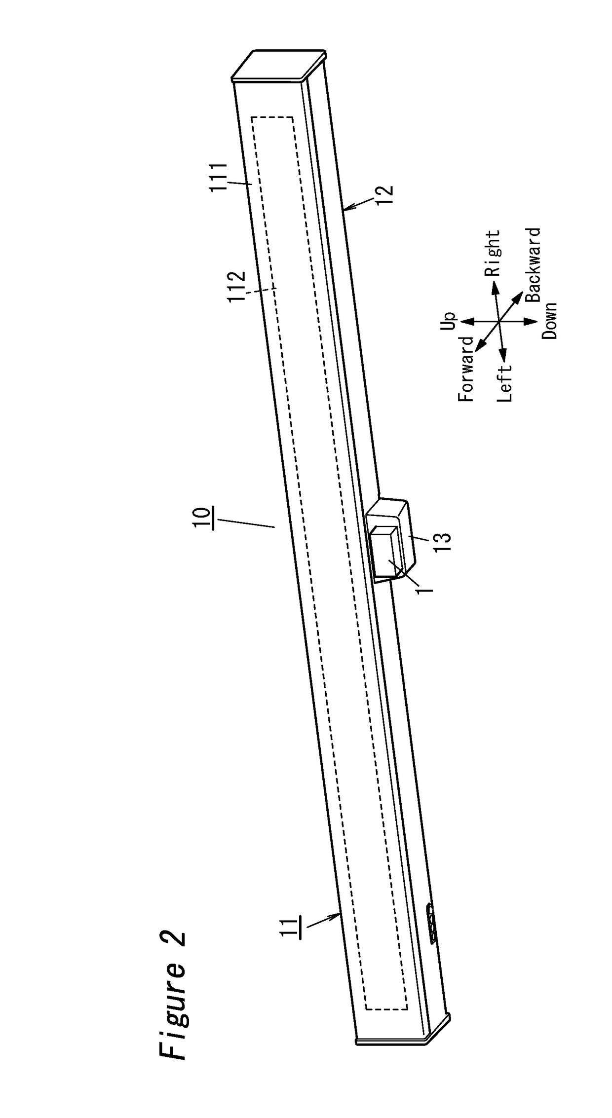
[0018]In the example of FIG. 1, a luminaire 10 according to the present embodiment is installed on a wall 100 of a landing 101A between a set of stairs 102A and a set of stairs 102B in a building. The directions of a radio wave sensor 1 and the luminaire 10 are defined by up, down, left, right, forward (fore) and backward (aft) shown by arrows in FIGS. 2 to 6, unless otherwise specifically noted in the explanation below. That is, as seen from the front of the luminaire 10 with the luminaire 10 installed on the wall 100 of the landing 101A, a vertical direction corresponds to the up-and-down direction, a lateral direction corresponds to the left-and-right direction, and a direction normal to the wall 100 corresponds to the fore-and-aft direction. The directions are not intended to li...


PUM


Abstract

A radio wave sensor includes a transmitting antenna configured to radiate radio waves, and a housing that is composed of dielectric material and faces the transmitting antenna. The housing has a first protrusion that protrudes from a region facing the transmitting antenna towards the transmitting antenna. The first protrusion has an entrance surface that allows the radio waves from the transmitting antenna to enter. The entrance surface contains a flat surface parallel to a surface of the transmitting antenna, and an inclined surface that inclines relative to the flat surface in a direction apart from the flat surface.

Description

CROSS REFERENCE TO RELATED APPLICATION[0001]This application claims the benefit and priority of Japanese Patent Application No. 2016-217361, filed on Nov. 7, 2016, the entire contents of which is incorporated herein by reference.TECHNICAL FIELD[0002]The disclosure relates generally to radio wave sensors and luminaires and, more particularly, to a radio wave sensor for detecting, e.g., human presence, which has a transmitting antenna configured to radiate radio waves, and a luminaire including the radio wave sensor.BACKGROUND ART[0003]In a related high frequency sensor, it has been known to use radio waves as one of wireless media (for example, JP 2007-104027 A (hereinafter referred to as “Document 1”)). The high frequency sensor described in Document 1 includes a transmitting antenna and a receiving antenna that are mounted on a substrate with a space between them, and a dielectric lens disposed forward of the transmitting and receiving antennae so as to cover the transmitting and r...

Claims


Application Information

Patent Timeline
Patent Type & Authority Applications(United States)
IPC IPC(8): H01Q3/44G01S13/06G01S13/04
CPCH01Q3/44G01S13/06G01S13/04H01Q23/00G01S13/56G01S13/88H01Q1/22H01Q1/42H01Q15/08
Inventor OHNO, TAKESHIIRIKAWA, ATSUSHIKATANODA, KANCHI
Owner PANASONIC INTELLECTUAL PROPERTY MANAGEMENT CO LTD
Why Eureka
Try Eureka