Self-Powered Wireless Switch and Application Thereof

a wireless switch and self-powered technology, applied in pulse technique, dynamo-electric machines, program control, etc., can solve the problems of increasing the operating cost of wireless controllers, wasting resources, and polluting the environment of controllers, so as to achieve reliable, safe and convenient

Active Publication Date: 2018-05-10
LIU YUANFANG
View PDF6 Cites 9 Cited by
  • Summary
  • Abstract
  • Description
  • Claims
  • Application Information

AI Technical Summary

Benefits of technology

[0008]The invention is advantageous in that it provides a self-powered wireless switch which is reliable, safe, and convenient with a remote switch, and can be widely used in everyday life.

Problems solved by technology

Even though such wireless controllers bring us convenience, thousands of conventional wireless controllers will pollute our environment and waste our resources.
Firstly, the wireless controller must be powered by batteries as its power source.
Therefore, the user must frequently replace the old batteries with new batteries after a period of time usage.
The operating cost for the wireless controller will be significantly increased by the batteries.
Since most of the batteries are disposable, the old batteries will pollute our environment.
Accordingly, land pollution is aggravated because of the wasted electronic components, such that many countries issue strict environmental regulations for those electronic wastes.
The installation not only takes times but also wastes lots of different materials.
More importantly, it is impossible to re-locate the controlling switch.
Otherwise, the wall must be damaged to form another wire running groove for the new electrical wire.
Safety concerns are other issues that the switch box and the PVC wire sleeve must provide moisture prevention and explosion protection.
However, the existing wireless switch has several drawbacks.
(2) It is a hassle to find the wireless switch as it is considered as a portable device to be stored at any location of the building.
Therefore, the user must replace the batteries frequently after a period of time.
Otherwise, the battery acid will leak out of the battery to pollute the environment and to shorten the service life span of the battery.
As result, the wireless switch cannot be widely used due to the above drawbacks.

Method used


Image

  • Self-Powered Wireless Switch and Application Thereof
  • Self-Powered Wireless Switch and Application Thereof
  • Self-Powered Wireless Switch and Application Thereof

Examples


fourth embodiment

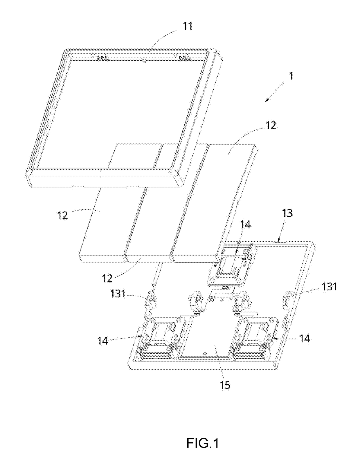
[0324]Accordingly, an assembling method for the self-powered wireless switch is illustrated, wherein the method further comprises the steps of assembling the self-powered wireless switch module assembly 10C for performing the operations of power generation and wireless communication, and assembling the switch panel 12C, designed according to the self-powered wireless switch module assembly 10C, with the self-powered wireless switch module assembly 10C. The step of assembling the self-powered wireless module assembly further comprises the steps of assembling the control panel 15C for regulating the electrical energy and sending out wireless control signal, and assembling the micro generator 14C for performing the power generation.

[0325]In particular, in the steps of assembling the control panel 15C for sending out wireless control signal, the structure of the control panel 15C is similar to that of the control panel 15C of the third preferred embodiment, such that the steps further ...

third embodiment

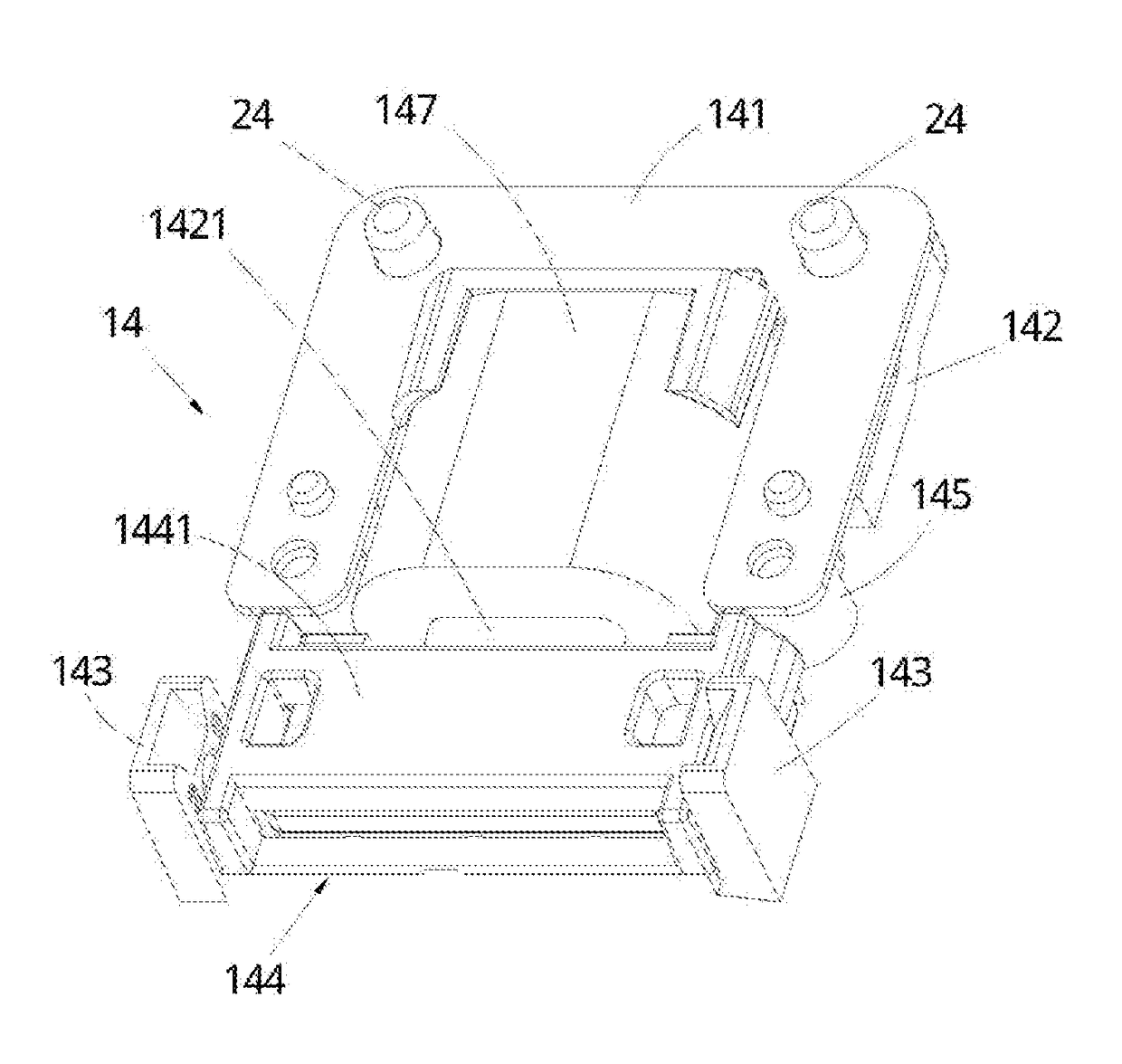
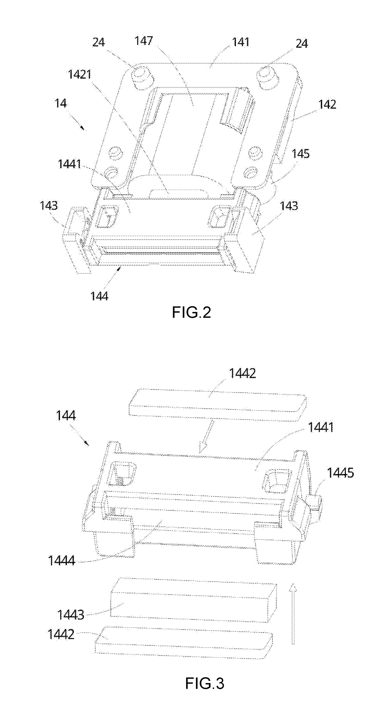
[0327]The steps of assembling the micro generator 14C further comprise the steps of assembling the coil assembly. In particular, the step of assembling the coil assembly further comprises the steps of coupling one end of the swinging arm 148C to the mounting arms 1414C of the H-shaped resilient member 141C via fastening members respectively, coupling the mounting arms 1414C of the resilient member 141C at the opposite side thereof to the engaging arms 1442C of the T-shaped coil core 142C, sleeving the core cover 1448C at the core arm 1421C of the T-shaped coil core 142C, winding the magnetic coil 147C around the one-piece frame at the coil frame 1447C thereof, winding the magnetic coil 147C around the core arm 1421C of the coil core 142C to a position adjacent to the core cover 1448C; extending the core arm 1421C of the T-shaped coil core 142C to distal end of the core arm 1421C, such that the core arm 1421C is disposed within the magnetic cavity 1446C to contact with the upper firs...

fifth embodiment

[0406]Accordingly, an assembling method for the self-powered wireless switch is illustrated, wherein the method further comprises the steps of assembling the self-powered wireless switch module assembly 10D for performing the operations of power generation and wireless communication, and assembling the switch panel 12D, designed according to the self-powered wireless switch module assembly 10D, with the self-powered wireless switch module assembly 10D. The step of assembling the self-powered wireless module assembly further comprises the steps of assembling the control panel 15D for regulating the electrical energy and sending out wireless control signal, and assembling the micro generator 14D for performing the power generation.

[0407]In particular, in the step of assembling the control panel 15D for sending out wireless control signal, the structure of the control panel 15D is similar to that of the control panel 15D of the third preferred embodiment, such that the step further co...


PUM


Abstract

A self-powered wireless switch includes at least one micro generator and a control panel for transmitting wireless control signals. The micro generator includes a magnet assembly and a coil assembly which are arranged to be moved relatively to one another to generate an induced current within the coil assembly; the coil assembly including an iron core and a wire winding around the outside of the iron core to form a magnetic coil; the magnet assembly including a permanent magnet and magnet conductive plates arranged at two sides of the opposite magnetic poles of the permanent magnet. The self-powered wireless switch enables the magnetic assembly and the coil assembly to move relatively to one another and converts the mechanical energy to electricity, thereby achieving self-power generation and providing electricity to the control panel for transmission of the wireless control signals.

Description

CROSS REFERENCE OF RELATED APPLICATION[0001]This is a non-provisional application that claims the benefit of priority under 35 U.S.C. § 371 to international application number PCT / CN2015 / 087311, international filing date Aug. 18, 2015, wherein the entire content of which is expressly incorporated herein by reference.NOTICE OF COPYRIGHT[0002]A portion of the disclosure of this patent document contains material which is subject to copyright protection. The copyright owner has no objection to any reproduction by anyone of the patent disclosure, as it appears in the United States Patent and Trademark Office patent files or records, but otherwise reserves all copyright rights whatsoever.BACKGROUND OF THE PRESENT INVENTIONField of Invention[0003]The present invention relates to a wireless switch, and more particular to a self-powered wireless switch.Description of Related Arts[0004]With the advent of high technology, the electronic industry has experienced very significant growth that tha...

Claims


Application Information

Patent Timeline
Patent Type & Authority Applications(United States)
IPC IPC(8): H03K17/94H02K35/02H02K5/04G08C17/00
CPCH03K17/94H02K35/02H02K5/04G08C17/00G05B19/042G05B2219/25257
Inventor LIU, YUANFANG
Owner LIU YUANFANG
Why Eureka
Try Eureka