This helps you quickly interpret patents by identifying the three key elements:
Problems solved by technology
Method used
Benefits of technology
Benefits of technology
The patent text describes an in-vehicle network system that can connect to external devices or outside networks securely and maintain fast communication speed. It achieves both security and communication speed objectives. This technology can be useful in ensuring the safety and reliability of vehicle-based networks.
Problems solved by technology
Incidentally, in a case where the external device is connected to a network built by the bus as described above, the driving support device of the related art does not increase a security level of data communication in the network.
With the development of information technology, there are various types of external devices, and therefore, the number of external devices in which a problem may be caused is increasing.
Further, the external device in which a problem may be caused is, for example, a non-genuine device that is not approved by the manufacturer of the vehicle.
Thus, when the security level does not increase in a case where the external device in which a problem may be caused is connected to the bus, an in-vehicle network or a control device or the like connected to the network is likely to be affected.
Further, such a problem is not limited to a case where the external device in which a problem may be caused is connected to a bus which is a physical communication line, and a problem may also be caused in a case where the external device is connected to a virtual communication line.
Further, such a problem may also be caused in a case where an in-vehicle network is connected to a network outside a vehicle via a wireless communication device, in addition to a case where the external device in which a problem may be caused is physically connected to the communication line.
Further, on the other hand, when the security level of data communication is always high in the entire network, the time needed for communication is likely to increase and a communication speed is likely to decrease.
Method used
Image
Click on the blue label to locate the original text in one second.
Reading with bidirectional positioning of images and text.
Examples
first embodiment
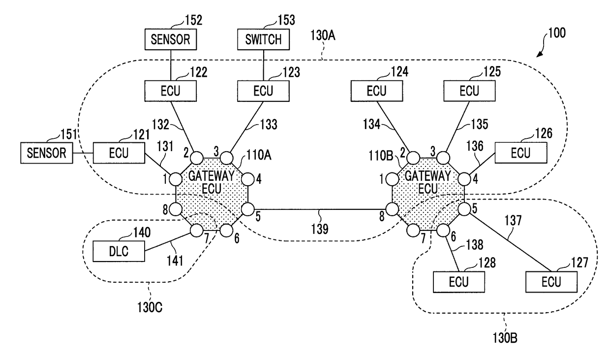
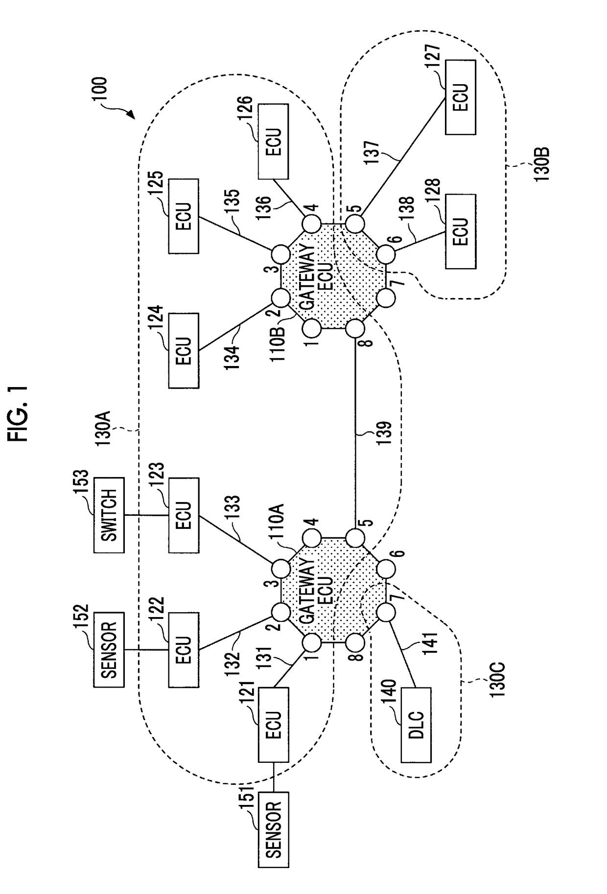
[0067]FIG. 1 is a diagram illustrating an in-vehicle network system 100 according to a first embodiment. The in-vehicle network system 100 is mounted on a vehicle.
[0068]The in-vehicle network system 100 includes relay devices (hereinafter referred to as gateway electronic control units (ECUs)) 110A, 110B, a plurality of controllers (hereinafter referred to as ECUs) 121, 122, 123, 124, 125, 126, 127, 128, communication lines 131, 132, 133, 134, 135, 136, 137, 138, 139, 141, and a data link connector (DLC) 140. Sensors 151, 152 are connected to the ECUs 121, 122, respectively, and a switch 153 is connected to the ECU 123.
[0069]The in-vehicle network system 100 uses, for example, an Ethernet protocol as a communication protocol. The communication lines 131, 132, 133, 134, 135, 136, 137, 138, 139, 141 do not indicate physical buses, and are virtual communication lines that build virtual local area networks (VLANs) 130A, 130B, 130C according to the Ethernet protocol.
[0070]The VLAN 130A i...
second embodiment
[0175]FIG. 11 is a diagram illustrating a relationship between a path for data to be transferred and an L2 switch, an L3 switch, and an L7 switch in an in-vehicle network system 200 according to a second embodiment.
[0176]The in-vehicle network system 200 according to the second embodiment has a configuration obtained by adding an ECU 129, a communication line 231, and a data communication module (DCM) 600 to the in-vehicle network system 100 according to the first embodiment.
[0177]The ECU 129 is connected to a port 7 of a gateway ECU 110B via the communication line 231. In the second embodiment, the ECU 129 is used as an example of a connector capable of connecting the DCM 600.
[0178]The VLAN 130D is built by the communication line 231, and the gateway ECU 110B and ECU 129 are connected thereto. The communication line 231 is an example of a second communication line. In FIG. 11, anything is not connected to the DLC 140.
[0179]Since a configuration other than the above-described config...
PUM
Abstract
An in-vehicle network system includes a plurality of first controllers; a plurality of first communication lines, the first communication lines being respectively connected to the first controllers; a connector that connects an external device or a wirelesscommunication device; a connection communication line that is connected to the connector; and a first relay device that relays between the first communication lines and the connection communication line. The first relay device is configured to determine whether a security level in data communication between the first controllers is increased according to a type of the external device or a communication state of the wirelesscommunication device in a state in which the external device or the wirelesscommunication device is connected to the connector, and the first relay device is configured to increase the security level when the first relay device determines that the security level is increased.
Description
INCORPORATION BY REFERENCE[0001]The disclosure of Japanese Patent Application No. 2016-216625 filed on Nov. 4, 2016 including the specification, drawings and abstract is incorporated herein by reference in its entirety.BACKGROUND1. Technical Field[0002]The disclosure relates to an in-vehicle network system.2. Description of Related Art[0003]In the related art, there is a driving support device that is connected to a bus (a global communication bus) that is connectable to a device outside a vehicle or a device brought from the outside of the vehicle (hereinafter, an external device) via the interface, which is a bus to which a plurality of control devices or sensors is connected. The driving support device performs driving support control for a vehicle based on information that is supplied from the control devices or sensors via the bus.[0004]Further, the driving support device continues to perform driving support control based on information that is supplied from the control device ...
Claims
Application Information
Patent Timeline
Application Date:The date an application was filed.
Publication Date:The date a patent or application was officially published.
First Publication Date:The earliest publication date of a patent with the same application number.
Issue Date:Publication date of the patent grant document.
PCT Entry Date:The Entry date of PCT National Phase.
Estimated Expiry Date:The statutory expiry date of a patent right according to the Patent Law, and it is the longest term of protection that the patent right can achieve without the termination of the patent right due to other reasons(Term extension factor has been taken into account ).
Invalid Date:Actual expiry date is based on effective date or publication date of legal transaction data of invalid patent.

