
Apparatus, System and Method to avoid the night-time of a driver

a technology of a driver and an apparatus, applied in the field of optoelectronic devices, can solve the problems of increasing the risk of accidents, increasing the stress of drivers driving vehicles on roads, and the problem of vision glare or dazzling has yet to be completely solved

Active Publication Date: 2018-05-10
CORREA CARLOS +1
View PDF0 Cites 10 Cited by
  • Summary
  • Abstract
  • Description
  • Claims
  • Application Information

AI Technical Summary

Benefits of technology

The patent is about a device and method to prevent the bright light from headlamps of vehicles in front of or behind a driver's vehicle, which can make it hard to see and can cause dazzle. The device uses intermittent light pulses from synchronized vehicles to protect the driver's vision and reduce the impact of headlamps. Overall, the technical effect is to improve driving safety and comfort.

Problems solved by technology

As is well known, people driving vehicles on roads are subjected to greater stress at night, because the lack of natural light adds to the glare, dazzling or temporary blindness caused by the light coming from the headlamps of vehicles moving in both the same and opposite direction of travel.
In every encounter with another vehicle, the driver's field of vision is reduced significantly by that glare, causing insecurity in driving as well as fatigue, increasing the risk of accidents.
The problem of vision glare or dazzling has yet to be completely solved.
Solutions tested to date include those dependent on road infrastructure, e.g. expressway lanes separated by a living enclosure, which are costly both from the point of view of their implementation and maintenance, and are not feasible for all roads due to topographic, climatic, economic factors, and others.

Method used


Image

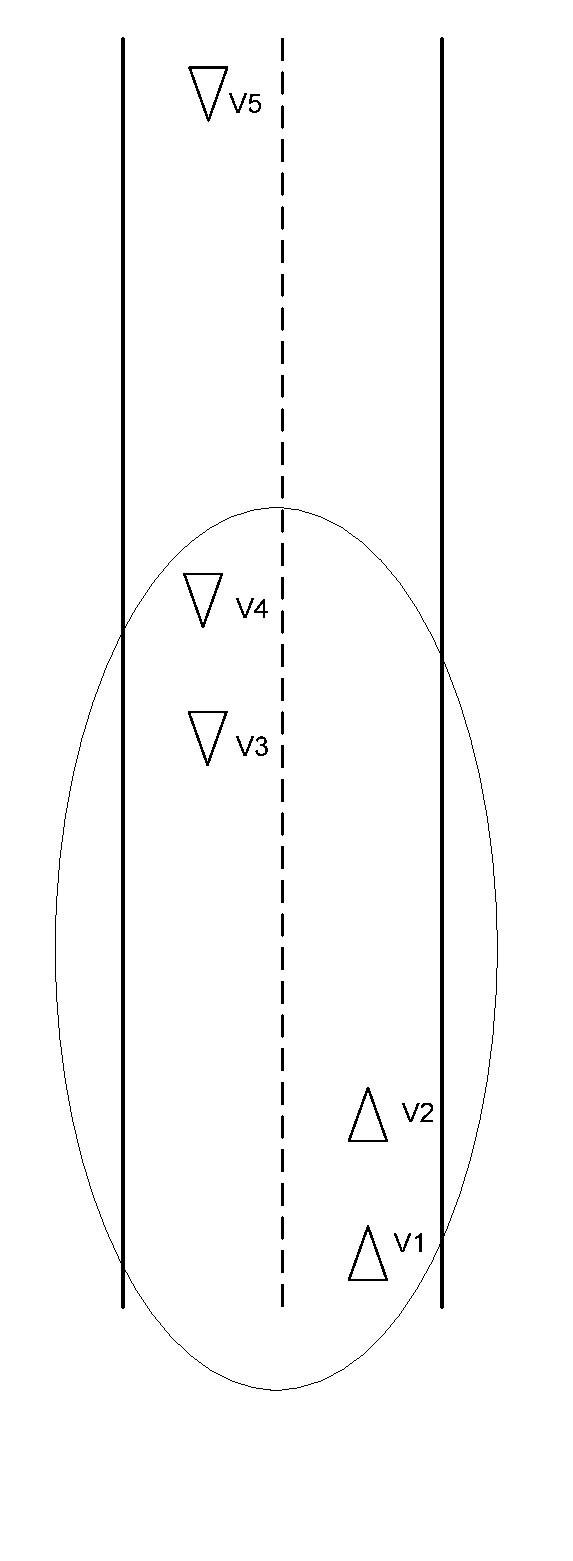
  • Apparatus, System and Method to avoid the night-time of a driver
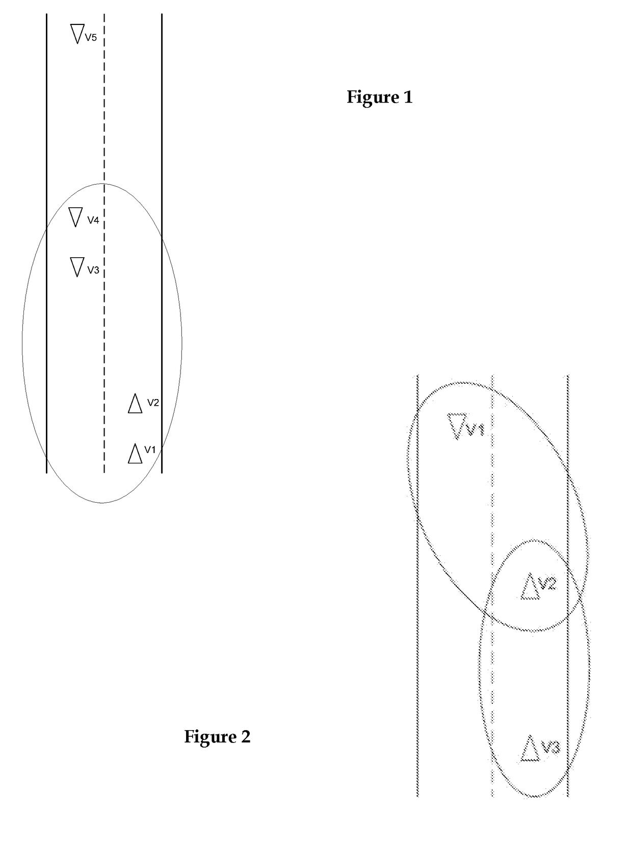
  • Apparatus, System and Method to avoid the night-time of a driver
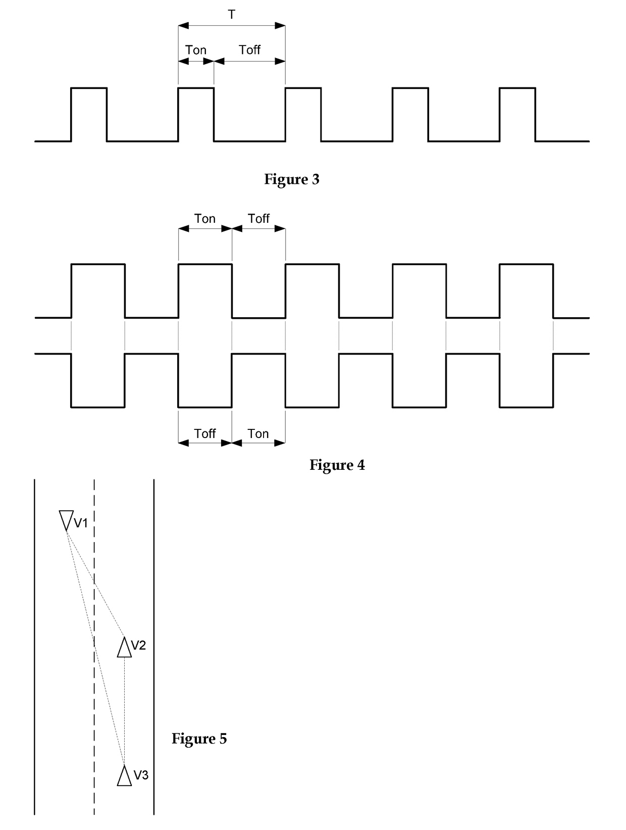
  • Apparatus, System and Method to avoid the night-time of a driver

Examples


case 1

[0487]Case 1: This is a non-synchronized NVE that has been formed due to the interaction between vehicles of an NVE synchronized with one or more “isolated” vehicles not synchronized with the former. At the decision point 328 vehicles from the synchronized NVE will have the “synchronized light detectionsignal active, therefore in said vehicles the “enable shifted emission” signal is activated at step 329 and then a waiting time at the decision point 330. Enabling the shifted emission in step 329 is intended, in this case, for the vehicle to transmit information to the “isolated” vehicles as we shall see below. In “isolated” vehicles, as no synchronized light is detected, the sequence passes from the decision point 328 to step 351 where the “enable shifted emission” signal is deactivated. Then in step 352 the sequence initiates a cycle which will be controlled by the counter XIII in step 354, a cycle which can be interrupted by detecting a light pulse whose positive edge falls on t...

case 2

[0490]Case 2: When in any of the non-synchronized NVE vehicles the “synchronized light detection” signal is active, the sequence in each of said vehicles will go from step 328 to step 351 where the ““Will be disabled. Then, from step 352, the sequence enters a cycle controlled by the counter XIII in step 354, which cycle in this case 2 will only be interrupted when said counter reaches the value corresponding to the time “t13”. This is because in this case 2 there are no vehicles coming from a synchronized NVE that emit their displaced light pulses. When the counter XIII reaches the value corresponding to the time “t13” the sequence passes to the part of the diagram corresponding to the application of the second strategy in order to be able to solve the synchronization of this NVE whose conformation is not enough to establish differences of “hierarchy” in vehicles. The description of that part of the diagram will be done after describing the remaining “cases”.

case 3

[0491]Case 3: This is a non-synchronized NVE that is formed from the confiding union of two synchronized NVEs whose respective vehicles are not synchronized with each other. Said non-synchronized NVE starts when the closest vehicles of both synchronized NVEs begin to interact with each other. Once in these non-synchronized NVE initiating vehicles, the “unsynchronized flashing light” signal is activated in all of them, the sequence including 322, 322A, 323, 323, 324, 325, 326, 327, 328, . . . at decision point 328 said “initiator” vehicles will have the “synchronized light detection” signal active and then the sequence will go to step 329 where each vehicle is enabled to emit pulses of light shifted in phase (pulses that in This case fulfills the function of enabling, if necessary, the protection of vision extended in the first potential successors, predicting that the NVE from which they come may be the one that has to change phases). Then at the decision point 330 the wait time han...


PUM


Abstract

An Optoelectronic apparatus, systems and methods to avoid the night-time dazzling of a driver's vision produced by the glare from the headlights of other vehicles. The disclosed embodiments include:(a) Intermittent lighting to illuminate the road, at least at times when glare should be avoided, as a substitute for the conventional continuous illumination produced by vehicle headlamps;(b) Synchronization of such intermittent illumination so that vehicles traveling in the same direction exhibit the same intermittent illumination phase and vehicles in opposite directions exhibit opposite intermittent illumination phases;(c) Protection of the driver(s) vision by preventing or attenuating at regular intervals of time the arrival of light into their eyes, including intermittent light pulses received from the already synchronized incoming vehicles;(d) Protection of the driver(s) vision by preventing or attenuating, at regular intervals of time, the arrival of reflected light, via rear-view mirrors, to their eyes, such protection including intermittent light pulses received from the already synchronized vehicles circulating in the same direction and behind said vehicle.

Description

CROSS-REFERENCE TO RELATED APPLICATIONS[0001]This application claims priority to co-pending U.S. Provisional patent application Ser. No. 62 / 419,667 titled “Metodos y Sistemas para evitar el Problema del Encandilamiento Nocturno en Ruta”, filed on Nov. 9, 2016 and to application Ser. No. 62 / 442,096 titled “Metodos y Sistemas para evitar el Problema del Encandilamiento Nocturno en Ruta”, filed on Jan. 4, 2017 the disclosure of which is herein incorporated by reference in their entirety, and in each case have for which accurate English translations have been made available.PATENTS CITED[0002]The following documents and references are incorporated by reference in their entirety, Fleury (U.S. Pat. No. 9,079,532), Badewitz (U.S. Pat. No. 4,859,047), Stam (US Pat. Pub. No. 2003 / 0107323) and Wolff (U.S. Pat. No. 4,286,308).FIELD OF THE INVENTION[0003]The present invention relates in general to an apparatus, method and system to reduce night-time vehicle operation vision dazzling, and specif...

Claims


Application Information

Patent Timeline
IPC IPC(8): H05B37/02F21S41/64B60Q1/08B60W50/00
CPCH05B37/0281F21S41/645B60Q1/085H05B37/0218B60W50/0098B60Q2300/47B60Q1/143H05B47/11H05B47/16H05B47/105Y02B20/40H05B47/26
Inventor CORREA, CARLOSHOESE, EDUARDO
Owner CORREA CARLOS
Learn More