
High-pressure gas tank and movable body

a gas tank and movable technology, applied in the direction of battery/cell propulsion, vehicle discharging methods, vehicle sub-unit features, etc., can solve the problems of possible sealing failure and small amount of gas possible permeation, and achieve the effect of improving the sealing property, facilitating manufacturing, and increasing the pressure in the above minute spa

Active Publication Date: 2018-05-17
TOYOTA JIDOSHA KK
View PDF6 Cites 5 Cited by
  • Summary
  • Abstract
  • Description
  • Claims
  • Application Information

AI Technical Summary

Benefits of technology

The patent describes a high-pressure gas tank with a sealing mechanism to prevent gas leakage. However, the existing sealing mechanism may not always be effective and may lead to a reversal of pressures that can degrade the sealing property. To address this problem, the patent proposes a new sealing mechanism that allows for the discharge of gas that may be leaked from the tank body section via a slit, while preventing an increase in pressure in the space between the base and the valve. Additionally, the patent also suggests a positioning mark on the base of the tank to facilitate installation. The technical effects of this patent include improved reliability of the sealing mechanism and reduced manufacturing costs.

Problems solved by technology

However, even when the O-ring is used as described above, a slight amount of the gas possibly permeates the O-ring and is possibly leaked from an inner side to an outer side of the tank body section, which stores the high-pressure gas.
More specifically, when a pressure in a reverse direction from a pressurizing direction in design is applied to the O-ring, projection (deformation) or the like of the O-ring possibly occurs, which results in possible sealing failure.

Method used


Image

  • High-pressure gas tank and movable body
  • High-pressure gas tank and movable body
  • High-pressure gas tank and movable body

Examples


second modified example

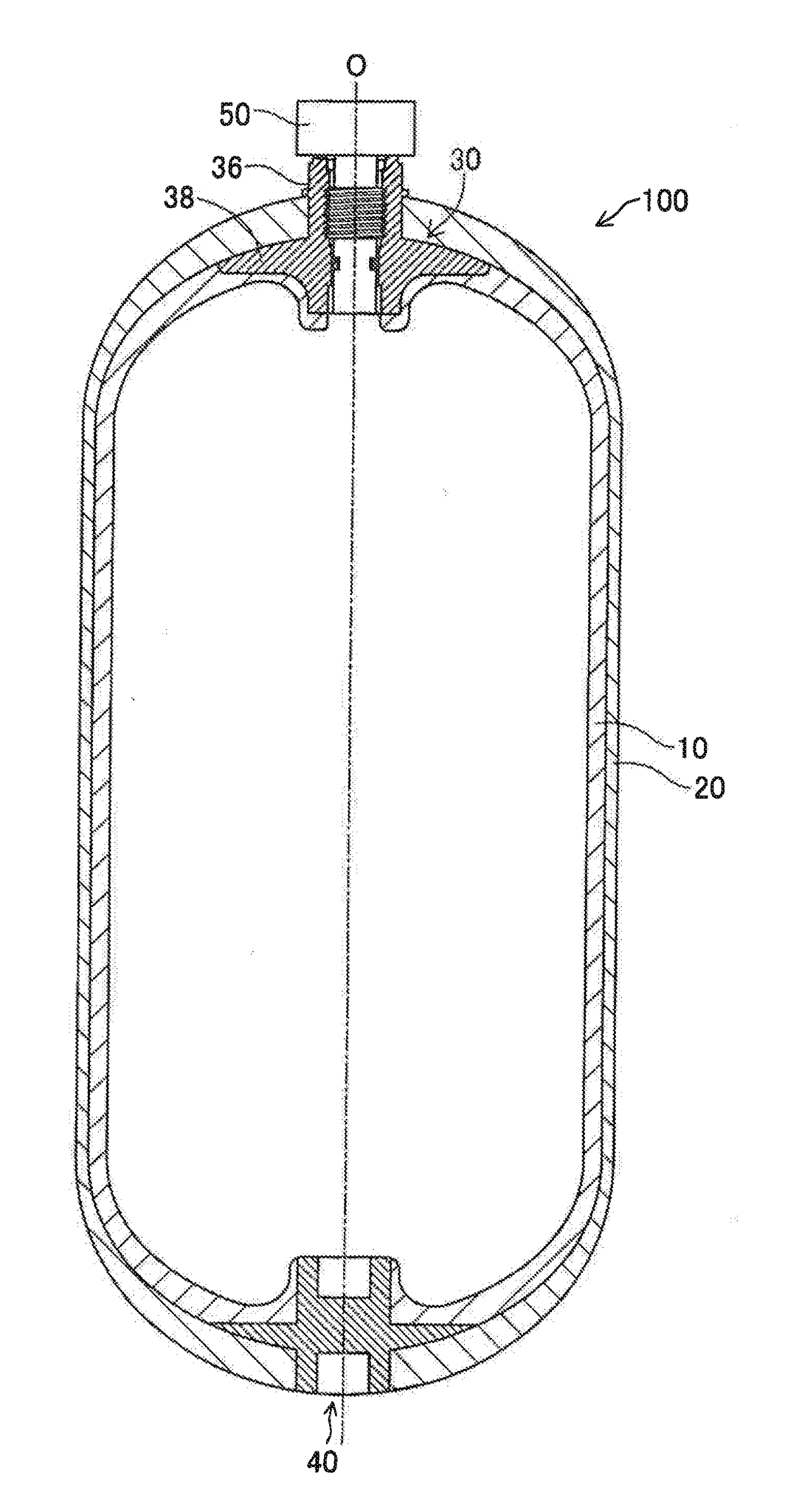
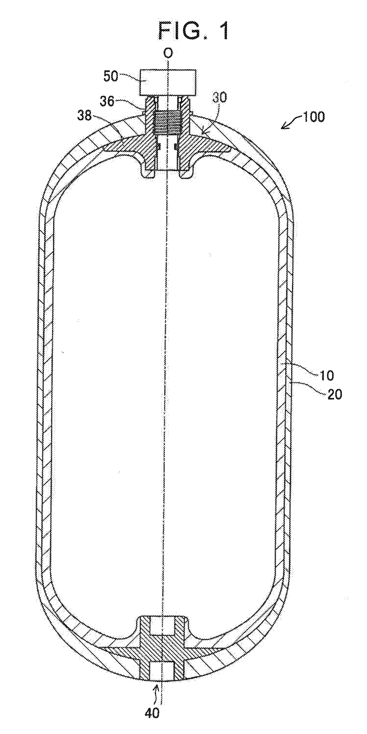
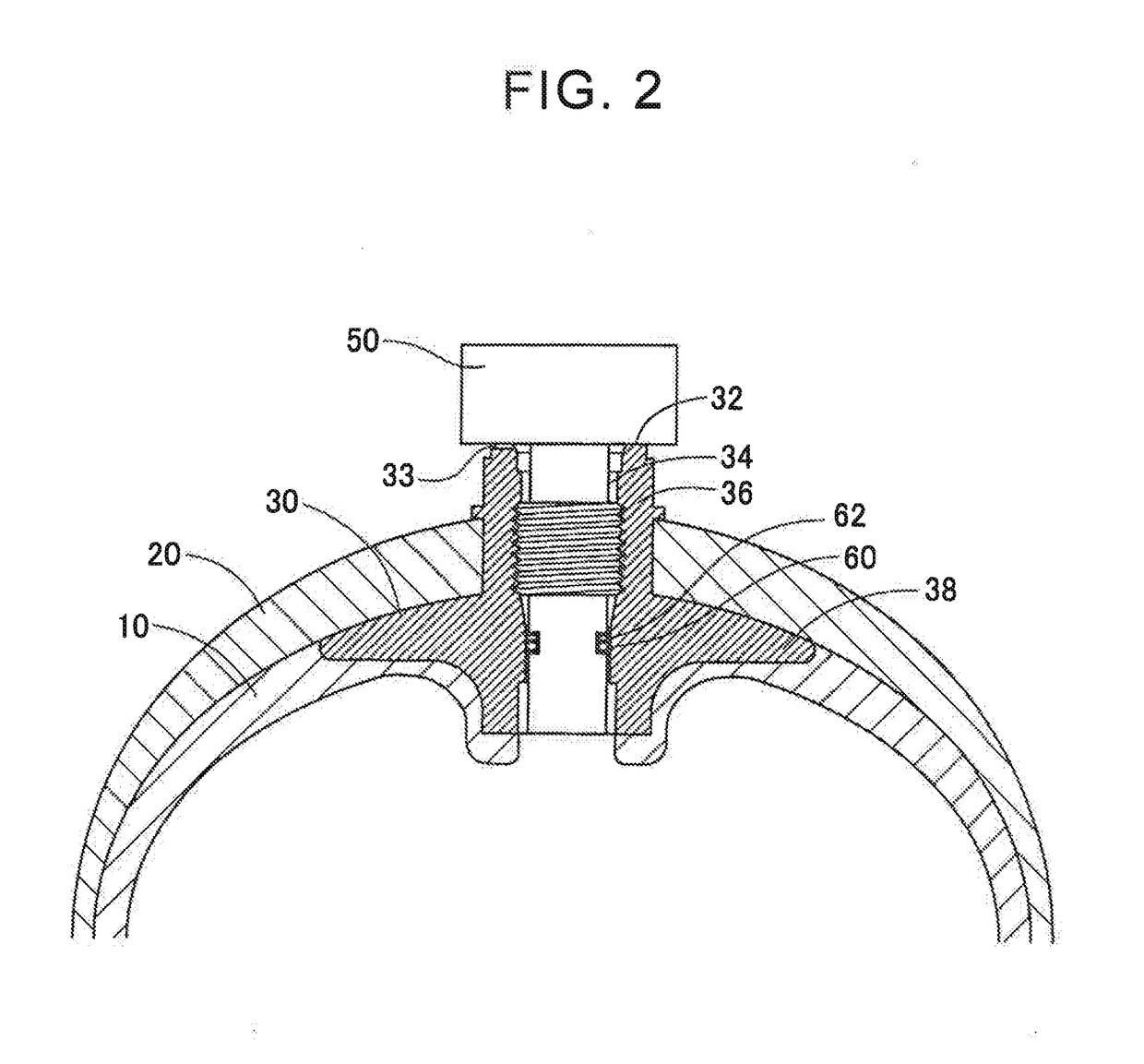
[0055] in the above embodiment, the seat surface 32 of the base 30 and the contact surface of the valve 50 are formed perpendicularly to the axis O of the high-pressure gas tank 100. However, a different configuration may be adopted therefor. Even when the above seat surface 32 and the above contact surface are not perpendicular to the axis O, in a cross section of the high-pressure gas tank 100 that includes the opening 31 of the slit communication hole and is perpendicular to the axis O, an acute angle defined by a straight line (corresponding to the straight line L1), which connects the highest point (corresponding to Mu in FIG. 5) in the vertical direction on an outer periphery of this cross section and the axis O, and a straight line (corresponding to the straight line L2), which connects the opening 31 of the slit communication hole and the axis O, only has to be 30° or less.

third modified example

[0056] in the above embodiment, the high-pressure gas tank 100 is arranged such that the axis O of the high-pressure gas tank 100 becomes parallel with the horizontal direction, and the slit 33 is formed such that the opening 31 of the slit communication hole is positioned near the lowest point in the vertical direction at this time. However, a different configuration may be adopted therefor. Even when different arrangement is adopted, the increase in the pressure P1 in the space 34 is suppressed by providing a slit. In this way, a similar effect of suppressing the degradation of the sealing property of the O-ring 60 is obtained.

fourth modified example

[0057] in the above embodiment, the O-ring 60 is used as a seal member that seals the gap between the inner peripheral surface of the base 30 and the outer peripheral surface of the valve 50. However, a different configuration may be adopted therefor. For example, any of various types of gaskets in shapes other than the O-ring can be used.


PUM

PropertyMeasurementUnit
angleaaaaaaaaaa
heightaaaaaaaaaa
radiusaaaaaaaaaa

Abstract

A high-pressure gas tank includes: a tank body section; a base attached to an opening of the tank body section; a valve attached to an opening of the base so as to open and close a gas supply-discharge port of the tank body section, a part of the valve being inserted in the base, and the valve having a contact surface that contacts a seat surface as a surface of an end of the base, the surface of the end of the base forming the opening of the base; and a seal member arranged between an outer peripheral surface of a portion of the valve that is inserted in the opening of the base and an inner peripheral surface of the base. A slit for forming a communication hole communicating between outside of the high-pressure gas tank and a space between the base and valve is provided.

Description

INCORPORATION BY REFERENCE[0001]The disclosure of Japanese Patent Application No. 2016-222883 filed on Nov. 16, 2016 including the specification, drawings and abstract is incorporated herein by reference in its entirety.BACKGROUND1. Technical Field[0002]The disclosure relates to a high-pressure gas tank and a movable body on which the high-pressure gas tank is mounted.2. Description of Related Art[0003]As a tank that stores and seals high-pressure gas therein, a tank that includes: a tank body section that forms a space for storing the gas; a base that is attached to an opening of the tank body section; and a valve that is attached to the base has been known. In such a tank, in order to secure a gas sealing property, a sufficient sealing property is desirably secured in a connection section between the base and the valve. As a structure of securing the sealing property of the connection section between the base and the valve, a configuration of arranging an O-ring between an outer p...

Claims


Application Information

Patent Timeline
Patent Type & Authority Applications(United States)
IPC IPC(8): F17C13/04F17C1/00B60K15/03B60L11/18
CPCF17C13/04F17C1/00B60K15/03006B60L11/1896F17C2201/0109F17C2201/035F17C2203/011F17C2203/0604F17C2203/0619F17C2203/0663F17C2203/066F17C2205/0323F17C2205/0391F17C2221/012F17C2270/0184F17C2270/0178B60K2015/03256B60K2015/03315F17C1/06F17C1/16F17C13/002F17C2270/0168F17C2223/035F17C2223/0107F17C2205/0388F17C2205/0302F17C2201/056B60Y2400/202B60K2015/03026B60K2015/03046B60K2015/0634Y02T90/16B60L50/71F17C2205/0305F17C2209/2118F17C2209/2154F17C2223/0123F17C2223/036Y02E60/32Y02T90/40
Inventor EMORI, SAKUMA
Owner TOYOTA JIDOSHA KK
Learn More