Method and system for determining a 3D position of an object in space

a technology of space and object, applied in the field of methods and systems, can solve the problems that methods and systems still leave room for improvement, and achieve the effect of improving accuracy

Active Publication Date: 2018-05-17
CARL ZEISS IND MESSTECHN GMBH
View PDF0 Cites 5 Cited by
  • Summary
  • Abstract
  • Description
  • Claims
  • Application Information

AI Technical Summary

Benefits of technology

[0008]Against this background, it is an object of the present invention to provide a method and a system for determining a 3D position of an object in space with improved accuracy.

Problems solved by technology

The known methods and systems still leave room for improvement, especially with respect to accuracy, detection speed and costs of implementation.

Method used


Image

  • Method and system for determining a 3D position of an object in space
  • Method and system for determining a 3D position of an object in space
  • Method and system for determining a 3D position of an object in space

Examples


Embodiment Construction

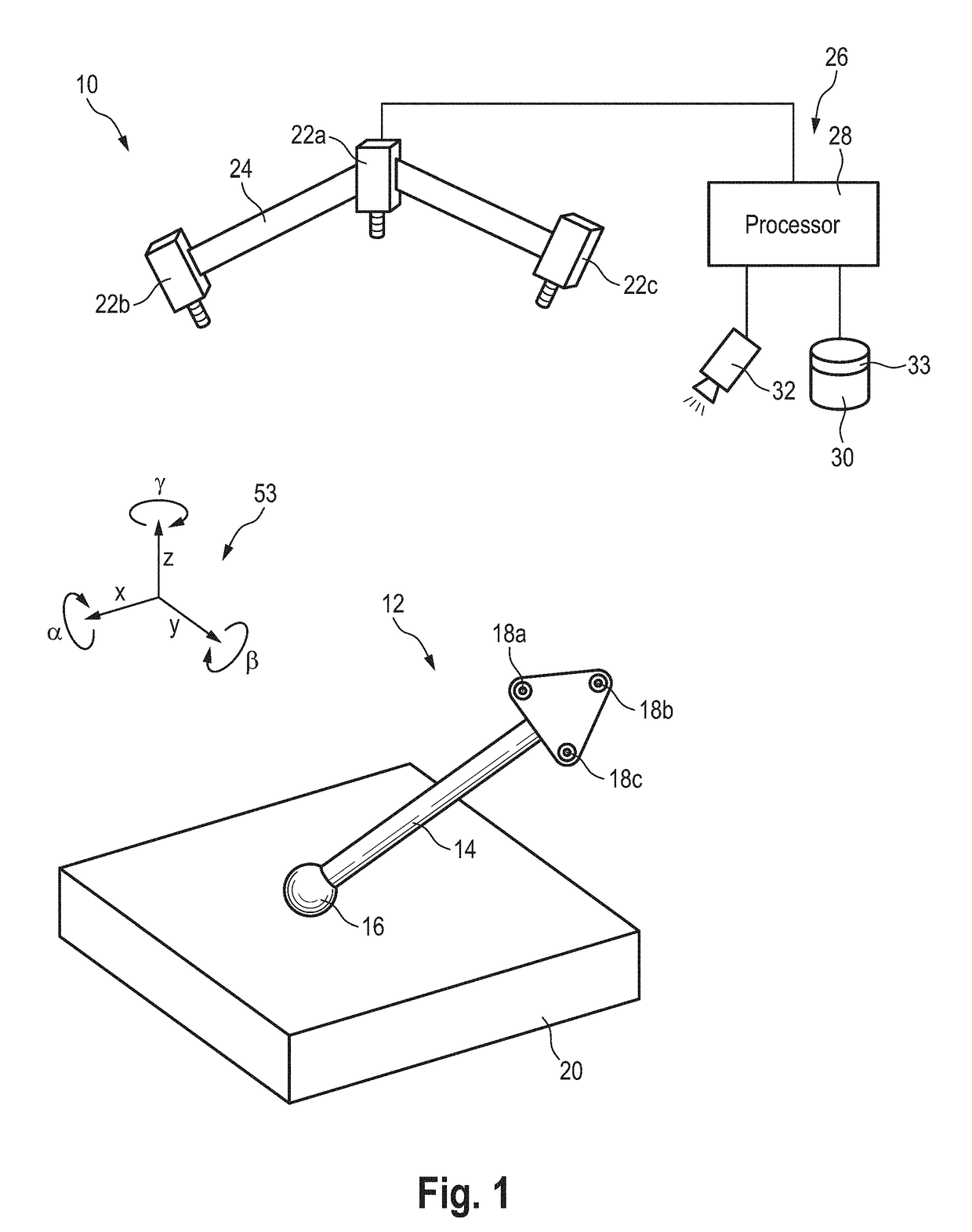
[0046]In FIG. 1, an exemplary embodiment of the new system is shown I a simplified form and designated by reference number 10 in its entirety. System 10 is designed and configured for detecting the 6-DOF-pose including the 3D position of a hand-operated tool 12. Accordingly, tool 12 is an object having a position and an orientation in space, which is to be determined by means of system 10. System 10 may implement exemplary embodiments of the new method, as will be explained in the following.

[0047]In this exemplary embodiment, tool 12 comprises a handle 14 which can be held and operated by a human or a robot (not illustrated). A ball 16 is arranged on a distal end of handle 14. At the proximal end, a plate carrying three artificial markers 18a, 18b, 18c is arranged. In this exemplary embodiment, tool 12 is designed and configured for identifying measurement points on a measurement object 20, such as a car body part or any other measurement object. Accordingly, system 10 and tool 12 t...


PUM


Abstract

A specimen of an artificial marker is arranged on an object, the position of which is to be determined. The artificial marker defines a nominal marker pattern with nominal characteristics. The specimen embodies the nominal marker pattern with individual characteristics. One or more images of the specimen are captured while the specimen is arranged on the object. An image representation of the specimen is analyzed using a data set. The data set comprises measured data values representing the individual characteristics as individually measured on the first specimen. Position values representing a 3D position of the specimen relative to a coordinate system are determined. A 3D position of the object is determined based on the position values of the specimen.

Description

CROSS-REFERENCE TO RELATED APPLICATIONS[0001]The present application is a continuation-in-part of U.S. Ser. No. 15 / 351,679 filed on Nov. 15, 2016 and claims priority from this prior application. The present application further claims priority under the Paris Convention from German patent application No. 10 2017 105 158.9 filed on Mar. 10, 2017. The whole content of these prior applications is incorporated herein by reference.BACKGROUND OF THE INVENTION[0002]The present invention relates to a method and a system for determining a 3D position of an object in space using one or more 2D artificial markers having defined features. At least one such marker is arranged on the object and at least one image of the artificial marker is captured while the at least one marker is arranged on the object. Using image processing technologies, a 3D position and, in some preferred implementations, a 3D-orientation of the artificial marker in space can be determined.[0003]Determining both 3D position ...

Claims


Application Information

Patent Timeline
Patent Type & Authority Applications(United States)
IPC IPC(8): G06T7/73
CPCG06T7/73G06T2207/30204G06T2207/10024G06T2207/30164
Inventor KRASZEWSKI, MACIEJHAVERKAMP, NILSGRZESIAK, ANDRZEJ
Owner CARL ZEISS IND MESSTECHN GMBH
Why Eureka
Try Eureka