Remote-control device comprising a portable remote control and a wall mounting

Active Publication Date: 2018-05-17
SOMFY ACTIVITES SA
View PDF0 Cites 6 Cited by
  • Summary
  • Abstract
  • Description
  • Claims
  • Application Information

AI Technical Summary

Benefits of technology

The patent describes a technical solution for improving the stability and secure anchoring of a portable remote control to a mounting surface. This is achieved through the use of an oblique orientation of surfaces on the support and housing, which increases the contact area between them and reduces the risk of detachment. The recess in the housing matches the shape of the support head, ensuring a perfectly stable mounting. The front surface of the housing is equipped with an entry interface that is designed to prevent detachment. These technical features improve the reliability and durability of the remote control.

Problems solved by technology

However, it is observed with use that it is not always easy to attach the remote control, in particular because when approaching the wall, the user naturally presents the remote control with an incline that does not facilitate the insertion of the head of the mounting in the eyelet.
Furthermore, the size of the head of the mounting is intentionally reduced so as not to protrude too much from the surface of the wall, such that the anchoring is not very secure.
Thus, if the remote control is jostled, it tends to swing, or even leave its mounting.

Method used


Image

  • Remote-control device comprising a portable remote control and a wall mounting
  • Remote-control device comprising a portable remote control and a wall mounting
  • Remote-control device comprising a portable remote control and a wall mounting

Examples


Embodiment Construction

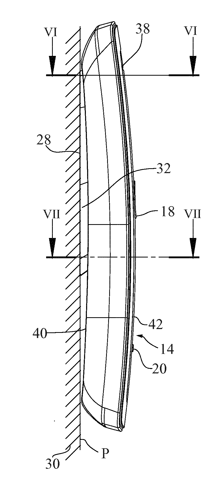
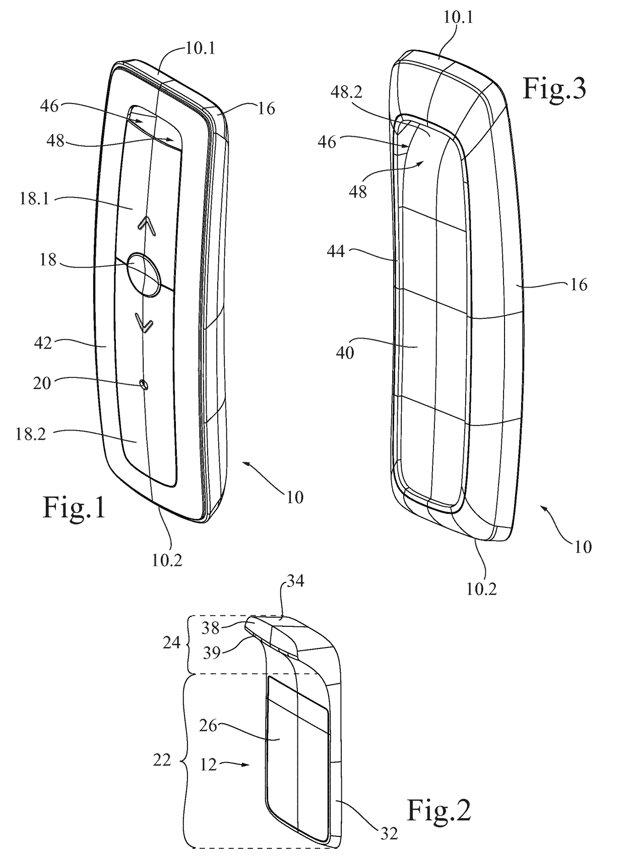
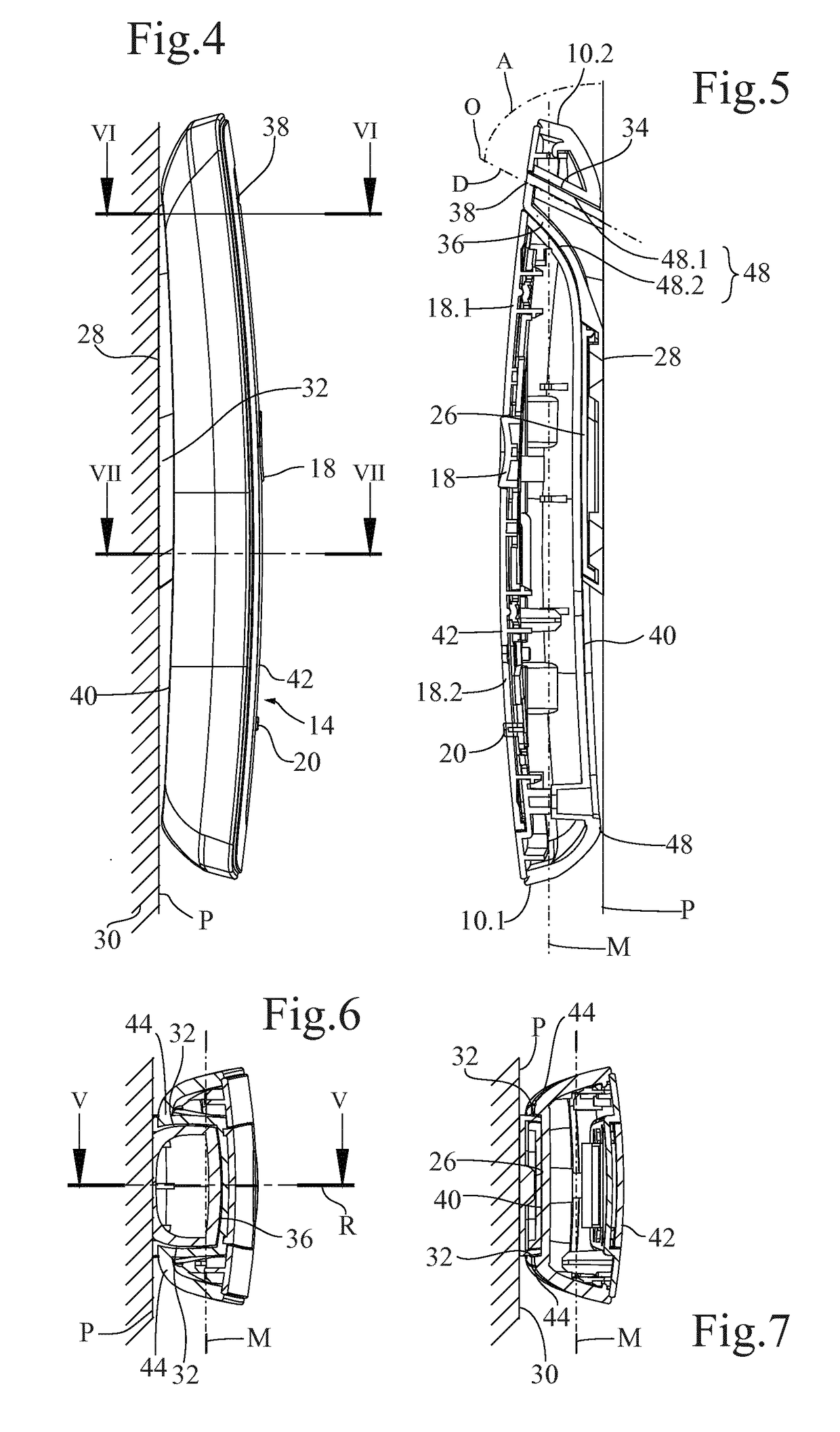
[0034]FIGS. 1 and 3 illustrate, from two different viewing angles, a portable remote control 10 intended to be anchored to a wall mounting 12 illustrated in FIG. 2, in an anchored position illustrated in FIGS. 3 to 5 and forming a remote control device 14 with the wall mounting.

[0035]In a manner known in itself, the portable remote control 10 is intended to be held in a user's hand and is used to control one or several pieces of home automation equipment (not shown) in a home automation installation from a variable position in a building, for example inside a room where the piece(s) of home automation equipment paired to the remote control are located.

[0036]The illustration of the portable remote control 10 has intentionally been limited to its housing 16, but one skilled in the art knows that such a remote control comprises an electronic control circuit connected to an entry interface, which is recognized here as having three keys18, 18.1, 18.2, if applicable a visual interface, he...


PUM


Abstract

The invention relates to a remote-control device (14) which comprises a portable remote control (10) and a wall mounting (12), the portable remote control (10) comprising a housing (16) having a rear surface (40) and a front surface (42), located on either side of and at a distance from a median plane (M) of the housing (16), the housing (16) including a recess (48) open at least on the rear surface (40), the wall mounting (12) having a surface (28) for bearing against a wall along a bearing plane (P) and a head (24) projecting from the bearing plane (P), the head (24) penetrating into the recess (48) in an anchoring position of the portable remote control (10) so as to pass through the median plane (M) of the housing (16). The recess (48) is shaped so as to match the shape of the head (24). The head (24) projects in an upward oblique direction (D) relative to the bearing plane (P), and has at least one first oblique surface (34, 36) which, in anchoring position, is in surface contact with at least one first oblique wall (48.1, 48.2) of the recess (48). The recess (48) is preferably open on the front surface (42) of the housing (16) and forms a passage between the rear surface (40) and the front surface (42) of the housing (16), which thus forms an eyelet (46) defining the recess (48).

Description

TECHNICAL FIELD OF THE INVENTION[0001]The present invention relates to a remote-control device comprising a portable remote control and its wall mounting, in particular for remotely controlling home automation equipment in a building.BACKGROUND OF THE INVENTION[0002]The installation instructions for the Telis® remote control by the company Somfy® dated May 2006 and available at the address https: / / www.somfy.fr / file.cfm / notice telis1rts.pdf?contentID=389780 illustrate an example of a portable remote control, i.e., able to be held in the hand and move while remaining functional, therefore including at least one autonomous power source and means for remote wireless communication with home automation equipment, which can be anchored to a wall mounting, which can be positioned in any desired location, for example near the home automation equipment paired to the remote control, or at the entrance to a room, to store the remote control. To that end, the housing of the remote control has an...

Claims


Application Information

Patent Timeline
IPC IPC(8): H01H9/02H05K5/00H05K5/02
CPCH01H9/025H05K5/0086H05K5/0204H05K5/023H01H2231/032H01H2300/03Y02B90/20Y04S20/14
Inventor ESCURIER, PIERRELE GOUEFF, ALIZESTRUBI, FREDERICBAJARD, PHILIPPEDESAGRE, THOMAS
Owner SOMFY ACTIVITES SA
Why Eureka
Try Eureka