Apparatus for crack detection during heat and load testing

a technology for crack detection and apparatus, applied in the field of apparatus for crack detection during heat and load testing, can solve the problems of inability to automate the procedure, high temperature and mechanical load on the and many engineering materials such as components of gas turbine engines

Inactive Publication Date: 2011-10-13
NAT RES COUNCIL OF CANADA
View PDF3 Cites 26 Cited by
  • Summary
  • Abstract
  • Description
  • Claims
  • Application Information

AI Technical Summary

Benefits of technology

[0010]Applicant has discovered, unexpectedly, that thermographic imaging can be provided of a sample in situ within a standard TMF test rig or like heat and load test apparatus to detect and monitor cracks as they form. Furthermore a 360° view of the part is possible using reflectors. The thermographic imaging system may be complemented with image analysis software for detecting a number and / or size of cracks in the sample, for determining a temperature of the sample, for example as a part of a temperature feedback control loop, and / or for load control.

Problems solved by technology

Many engineering materials such as components of gas turbine engines are subjected to both high temperatures and mechanical loads.
Throughout the life of the engine, cracks can develop in engine components and grow as a result of this thermo and mechanical fatigue.
The primary disadvantages of acetate replication are that the procedure is labour intensive and cannot be automated.
Unfortunately, it is not possible to get an idea about the presence or state of development of cracks except by assigning numbers of cycles between the inspections, or by changes in the stress determined by the extensometer as a function of load.
Typically, once the stress changes with the load, the part has fatigued to nearly the point of failure.
The stochastic nature of the process makes the assignment unreliable.
It is known that fatigue in similar samples progress at markedly different rates, even in tightly controlled environments.
The expense and availability of the parts, skilled labour, time and equipment required to study development at key points in the process are practical issues that impact the decision, and in general this state of affairs impedes determinations of the properties of samples.
No equipment is shown for doing this, but, as the part is stated to be metal, and mechanical fatigue testing is performed resulting in microplastic deformations in the notched region, one would naturally expect that significant load bearing equipment would be required, but it is known that this equipment could leave 2 dimensions of the part exposed.
Naturally Ummenhofer et al. would want the heat applied to minimally influence the mechanical fatigue properties of the part, as thermal fatigue contributions are generally unwanted for materials that are not thermally cycled, and as thermal cycling changes the nature of fatigue.

Method used


Image

  • Apparatus for crack detection during heat and load testing
  • Apparatus for crack detection during heat and load testing
  • Apparatus for crack detection during heat and load testing

Examples


examples

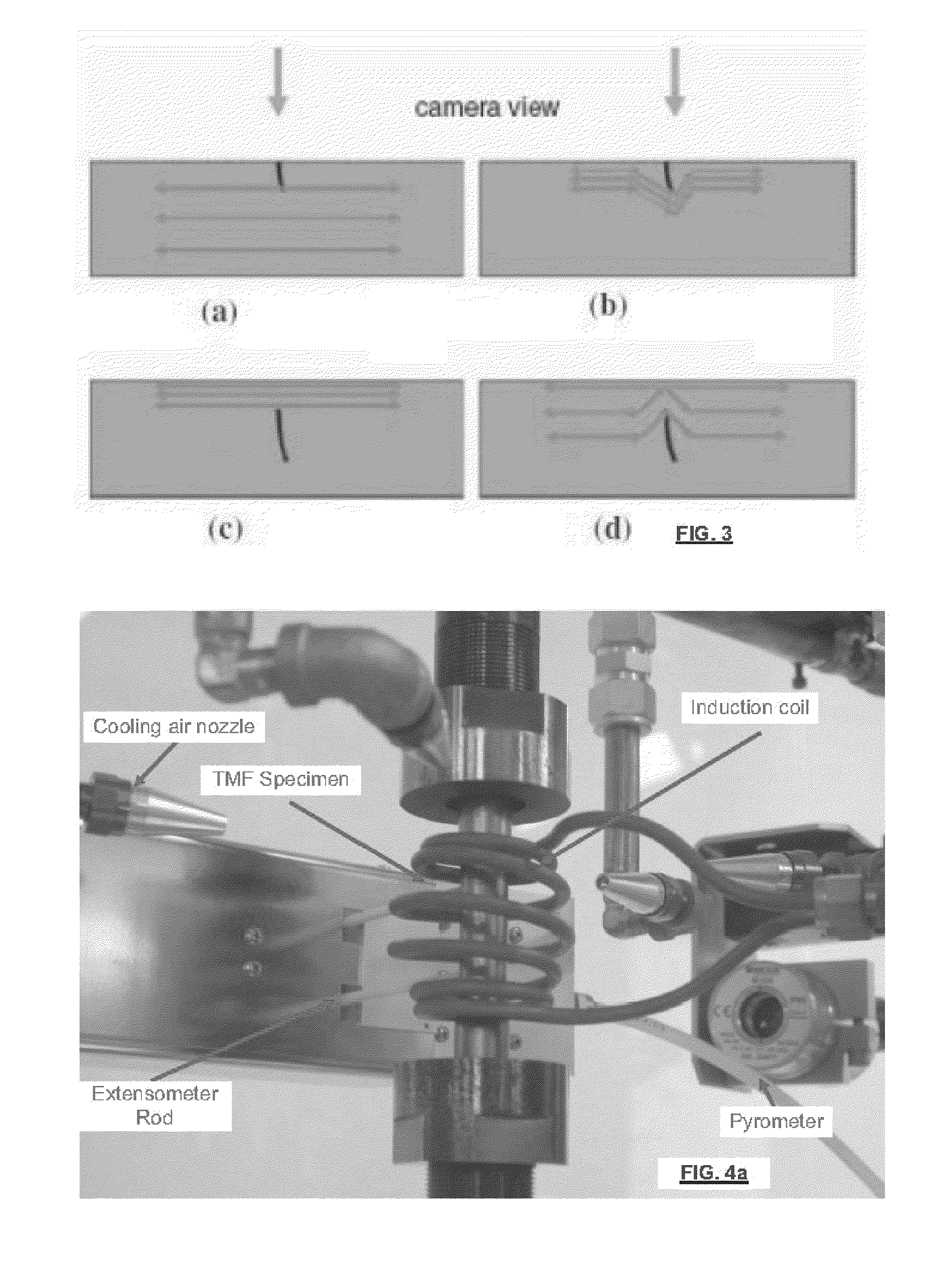
[0046]FIGS. 4a,b are two images showing an experimental heat and load test apparatus used for demonstrating the utility of the present invention. A MTS model 810 uniaxial servo-hydraulic test machine with a 100 kN load capacity was used as the load frame and actuator, to apply mechanical loading during the TMF test. The thermal loading was induced with an inductive helical coil powered by an Ameritherm Novastar 5 kW frequency generator. The strain was measured using a MTS model 654.54.11F high-temperature axial extensometer, while the temperature was measured using a Mikron MiGA5 infrared pyrometer. The control system consisted of a MTS model 493.01 digital controller running MTS 793 system software which was used for closed-loop control of both strain and temperature, and open-loop control of cooling air supplied to the sample.

[0047]The TMF test sample was machined from an inconel alloy. The sample had a length of ˜4″, a ˜½″ diameter. Prior to starting the TMF test, two black-body ...


PUM


Abstract

Material testing under variable heat and load while continuously monitoring crack formation is provided using an apparatus that permits thermal control somewhat uniformly over a conductive sample, while permitting a controlled load to be applied to the sample in tensional or flexural modes. Thermographic imaging of a sample in situ within a standard thermo-mechanical fatigue (TMF) test rig or other heat and load test apparatus is used to detect and monitor cracks as they form. A 360° sample view is possible. Image analysis software may identify, count and/or characterize cracks. Thermographic images may be analyzed to determine a sample temperature, e.g. for temperature feedback control. Essentially passive thermography is used with an inductive heating coil that surrounds at least 60% of a length of the sample, with at least two windings, the windings having thickness and pitch so that at least half the sample is in view.

Description

CROSS-REFERENCE TO RELATED APPLICATIONS[0001]This application claims the benefit of United States Provisional patent application U.S. Ser. No. 61 / 282,828 filed Apr. 7, 2010 the entire contents of which is herein incorporated by reference.FIELD OF THE INVENTION[0002]The present invention relates in general to material testing under variable heat and load, and, in particular, to an apparatus for heat and load testing that permits thermal control somewhat uniformly over a conductive sample, while permitting a controlled load to be applied to the sample in tensional or flexural modes, wherein the apparatus permits continuous monitoring of crack formation.BACKGROUND OF THE INVENTION[0003]Thermomechanical fatigue (TMF) is a standardized test used to determine a safe operating life for structural parts, especially those that are exposed to considerable temperature fluctuations when in use. Many engineering materials such as components of gas turbine engines are subjected to both high tempe...

Claims


Application Information

Patent Timeline
Patent Type & Authority Applications(United States)
IPC IPC(8): H04N5/30H04N7/18
CPCG01N25/72
Inventor GENEST, MARCDUDZINSKI, DAVID
Owner NAT RES COUNCIL OF CANADA
Why Eureka
Try Eureka