Image forming device

a technology of forming device and image, which is applied in the direction of printing and other printing apparatus, can solve the problems of reducing the quantity of ink discharged, remarkably reducing the image quality, etc., and achieves the effects of suppressing the pixel density of the image, prolonging the life of the head unit, and lowering the print quality

Active Publication Date: 2018-05-24
RISO KAGAKU CORP
View PDF1 Cites 9 Cited by
  • Summary
  • Abstract
  • Description
  • Claims
  • Application Information

AI Technical Summary

Benefits of technology

[0009]The present invention has been made in view of the above circumstances. It is an object of the present invention to provide an image forming device that continuously performs printing for a longer time without remarkably lowering the print quality even when a head unit is near its life end point.
[0014]With this configuration, in the image forming device, when the element operation count has reached or exceeded the warning threshold count that is smaller by the predetermined count than the threshold count, the image can be formed by suppressing the element operation count, and as a result, life of the head unit can be extended even before the life end point. Accordingly, it becomes possible to continuously print for a longer time without remarkably lowering the print quality even when the element operation count has reached or exceeded the warning threshold count and the head unit is near its life end point.
[0015]According to the second aspect of the present invention, to control the head unit to form the image by suppressing the element operation count, the processor generates the modified image data in which the element operation count is suppressed by performing either the thinning process that thins out the pixels that constitute the image or the pixel density reducing process that suppresses the pixel density of the image, and controls the head unit based on the generated modified image data. Even in such a case, the life of the head unit can be extended.
[0016]According to the third aspect of the present invention, when the element operation count is equal to or greater than the warning threshold count, the processor receives the instruction from the user whether to form the image by suppressing the element operation count or not. Moreover, when the element operation count reaches or exceeds the warning threshold count and the processor receives the instruction that the image is to be formed by suppressing the element operation count, the processor controls the head unit to form the image by suppressing the element operation count. Accordingly, in the image forming device, because the user can select whether the image is to be formed by suppressing the element operation count or without suppressing the element operation count, degree of freedom of selection can be increased and convenience offered to the user can be improved.

Problems solved by technology

As a result, the quantity of the ink discharged reduces, which lowers the image quality remarkably.

Method used


Image

  • Image forming device
  • Image forming device
  • Image forming device

Examples


first exemplary embodiment

(Configuration of Image Forming Device)

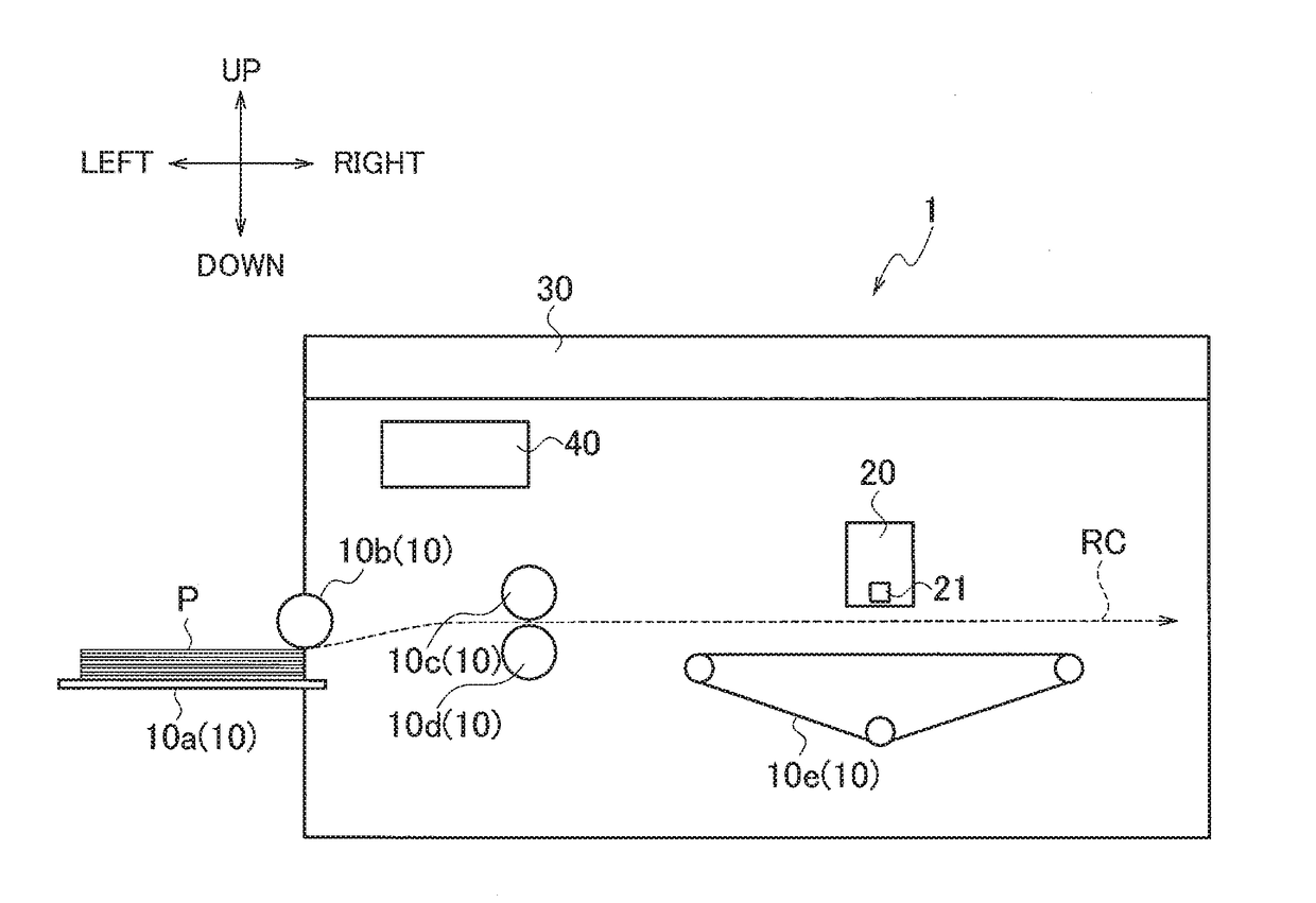
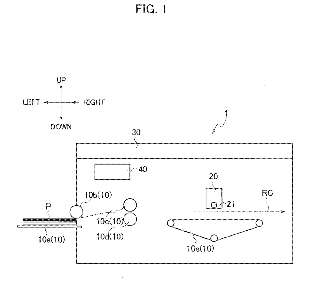
[0027]FIG. 1 is a schematic structural diagram of a configuration of an image forming device 1 according to a first exemplary embodiment of the present invention. In the following description, as shown in FIG. 1, up, down, left, and right depicted in FIG. 1 refer to up, down, left, and right directions respectively. In FIG. 1, a path indicated by a broken line is a conveying path RC via which a paper sheet P, that is a recording medium, is conveyed and a direction from the left to the right is a conveying direction.

[0028]The image forming device 1 forms an image by an element operation of each of elements 21 which will be described later.

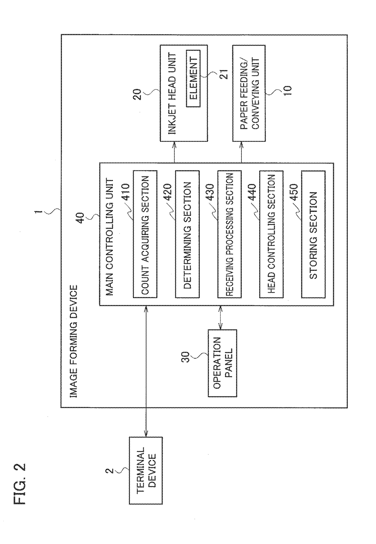
[0029]As shown in FIG. 1, the image forming device 1 includes a paper feeding / conveying unit 10, an inkjet head unit 20, an operation panel 30, and a main controlling unit 40.

[0030]The paper feeding / conveying unit 10 feeds and conveys the paper sheet P along the conveying path RC. The paper feeding / conveying un...

first modification

(First Modification)

[0080]An image forming device 1 according to a first modification of the first exemplary embodiment of the present invention will be described below.

[0081]In the first exemplary embodiment described above, when controlling the inkjet head unit 20 in the suppression mode, the head controlling section 440 performs the pixel density reducing process in which the pixel density of the image data is reduced, to generate the modified image data in which the element operation count is suppressed. In contrast, in the first modification, the head controlling section 440 generates, by performing a thinning process that thins out the pixels that constitute an image, the modified image data in which the element operation count is suppressed, and controls the inkjet head unit 20 based on the generated modified image data.

[0082]FIG. 5A is a schematic image obtained from image data before the thinning process is performed, and FIG. 5B is a schematic image obtained from the modif...

second modification

(Second Modification)

[0086]An image forming device 1 according to a second modification of the first exemplary embodiment of the present invention will be described below.

[0087]In the first embodiment described above, when the user inputs an instruction in the operation panel 30, the receiving processing section 430 receives the mode instruction data. In the second modification, the receiving processing section 430 receives mode instruction data when the user inputs an instruction in the terminal device 2 at the time of generating job data in the terminal device 2.

[0088]First, operation performed when the image forming device 1 has received the job data will be described. FIG. 6 is a flowchart of operations of the image forming device 1.

[0089]Note that, the operations performed at Steps S101 to S103 are the same as those performed at Steps S11 to S13 shown in FIG. 3 and description thereof is omitted.

[0090]When the determining section 420 determines that the highest cumulative value...


PUM


Abstract

An image forming device includes an inkjet head unit, a count acquiring section, a determining section, and a head controlling section. The inkjet head unit includes an element. The count acquiring section acquires, based on job data, an element operation count of the element. The determining section determines whether the element operation count is equal to or greater than a warning threshold count that is smaller by a predetermined count than a life threshold count corresponding to a life end point of the element. The head controlling section controls, when the element operation count is equal to or greater than the warning threshold count, the inkjet head unit to form an image by suppressing the element operation count.

Description

CROSS REFERENCE TO RELATED APPLICATION[0001]This application claims benefit of priority under 35 U.S.C. § 119 to Japanese Patent Application No. 2016-227418, filed on Nov. 24, 2016, the entire contents of which are incorporated by reference herein.BACKGROUND OF THE INVENTION1. Field of the Invention[0002]The present invention relates to an image forming device that includes a head unit having an element and forms an image by an element operation of the element.2. Description of the Related Art[0003]Conventionally, a configuration that includes a head unit having an element for forming an image is widely used in image forming devices such as inkjet printing machines and stencil printing machines.[0004]For example, in the inkjet printing machine, an element operation of the element causes the head unit to discharge ink and form an image on a recording medium such as paper sheet.[0005]The above-described element, when operated for a prescribed number of times, deteriorates and stops fu...

Claims


Application Information

Patent Timeline
Patent Type & Authority Applications(United States)
IPC IPC(8): B41J2/045B41M1/12
CPCB41J2/04513B41J2/0458B41J2/04581B41M1/12B41J29/393B41J2/0451B41J2/04536
Inventor TAKATA, ATSUSHI
Owner RISO KAGAKU CORP
Why Eureka
Try Eureka