Hardening apparatus for a long member, and a hardening method for a long member
- Summary
- Abstract
- Description
- Claims
- Application Information
AI Technical Summary
Benefits of technology
Problems solved by technology
Method used
Image

Examples
first embodiment
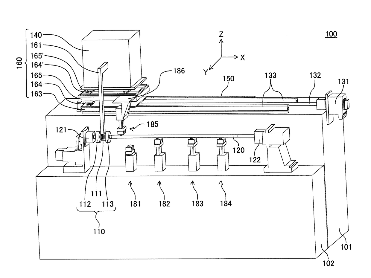
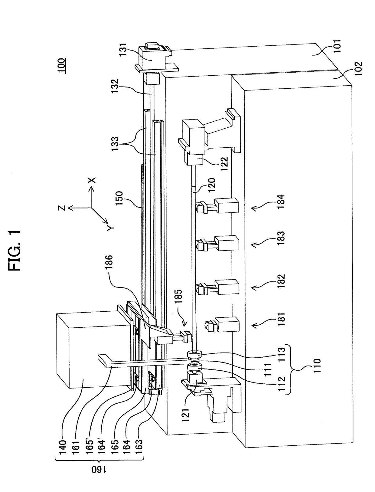
[0119]Hereafter, an example of a hardening apparatus according to one embodiment of the above-mentioned first the-present-invention (which may be referred to as a “first apparatus” hereafter) will be explained in detail, referring to drawings. In the present example, a case where a curve of the bent pipe is two-dimensional will be explained.
[0120]In addition, in the following explanation, a longitudinal direction of the bent pipe and the tracing gauge is defined as an X-axis direction, a direction which perpendicularly intersects with the X-axis direction in a horizontal plane is defined as a Y-axis direction, and a direction which perpendicularly intersects with these X-axis and the Y-axis is referred to as a Z-axis direction. Moreover, a direction toward the right side when the-present-invention apparatus is observed from its front side is defined as a positive direction in the X-axis direction, a direction toward the near side (direction toward an observer) when the-present-inven...
second embodiment
[0149]Hereafter, an example of a hardening apparatus according to another embodiment of the above-mentioned first present-invention apparatus (which may be referred to as a “second apparatus” hereafter) will be explained in detail, referring to drawings. In the present example, a case where the curve of the bent pipe is three-dimensional will be explained.
[0150]FIG. 9 and FIG. 10 are perspective views for showing the whole picture of the second apparatus 200 observed from its front side and back side respectively. Basically, the second apparatus 200 has the same configuration as that of the first apparatus 100 except for a point that it has a mechanism which enables tracing in the Z-axis direction since the curve of the bent pipe is three-dimensional as mentioned above. Therefore, in the following explanation, a configuration which is different from that of the first apparatus 100 will be explained in detail, and an explanation about the same configuration as that of the first appar...
third embodiment
[0163]Hereafter, an example of the hardening apparatus according to one embodiment of the above-mentioned second present-invention apparatus (which may be referred to as a “third apparatus” hereafter) will be explained in detail, referring to drawing sheets.
[0164]First, structure of the long member 1 having a hat-like cross-section as a workpiece which is a target of the hardening treatment by the third apparatus is shown in FIG. 12. (a) is a perspective view of the long member 1, and (b) is a sectional view of the long member 1 along a plane perpendicular to the longitudinal direction (X-axis direction) (plane parallel to a Y-Z plane).
[0165]The long member 1 comprises one top plate part 2, two sidewall parts 3, and two flange parts 4. The two sidewall parts 3 are respectively extending toward the same direction (in the present example, negative direction side of the Z-axis) from both ends of the top plate part 2 on the same one of two principal surfaces of the top plate part 2. The...
PUM
| Property | Measurement | Unit |
|---|---|---|
| Time | aaaaa | aaaaa |
| Weight | aaaaa | aaaaa |
| Shape | aaaaa | aaaaa |
Abstract
Description
Claims
Application Information
 - R&D Engineer
- R&D Manager
- IP Professional
- Industry Leading Data Capabilities
- Powerful AI technology
- Patent DNA Extraction
Browse by: Latest US Patents, China's latest patents, Technical Efficacy Thesaurus, Application Domain, Technology Topic.
© 2024 PatSnap. All rights reserved.Legal|Privacy policy|Modern Slavery Act Transparency Statement|Sitemap