
Dynamic entrance controlling system and dynamic entrance controlling method

Active Publication Date: 2017-10-19
CAL COMP ELECTRONICS
View PDF0 Cites 1 Cited by
  • Summary
  • Abstract
  • Description
  • Claims
  • Application Information

AI Technical Summary

Benefits of technology

The invention provides a system and method for controlling the entrance of people based on their identity recognition. This is done by using two wireless receiving devices to sense the movement of the person and determine their direction of movement. This information is then used to trigger the capture of the person's image and compare it with pre-stored information to conduct identity recognition. The main technical effect of this invention is to enhance the smoothness of people's mobility and provide efficient and accurate identity recognition.

Problems solved by technology

However, there is a problem in which the entrance guard cards may easily get lost, causing the risk on safety.
The system cannot make sure the man who conducts swiping is the man who owns the card, so that the person controls cannot be carried on exactly.
However, biometric techniques will essentially bring different problems.
However, the time needed for the fingerprint identification is longer.
If this kind of identification way is adopted, it will cause the problem of people stuck in line during the rush hours like commuting time, thus making the mobility of people in restrained areas been impeded.

Method used


Image

  • Dynamic entrance controlling system and dynamic entrance controlling method
  • Dynamic entrance controlling system and dynamic entrance controlling method
  • Dynamic entrance controlling system and dynamic entrance controlling method

Examples


first embodiment

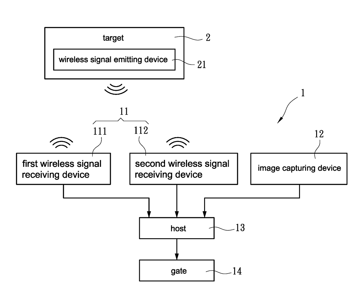
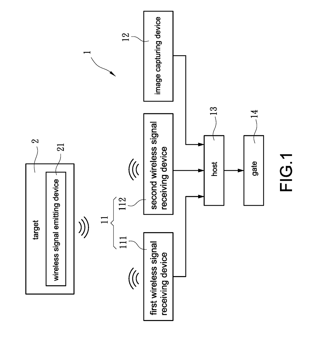
[0021]Refer to FIG. 1. FIG. 1 is a system block diagram of the invention. As shown in FIG. 1, the invention discloses a dynamic entrance controlling system 1 (system 1 as abbreviation in the following). In one embodiment of the invention, the system 1 mainly includes two wireless signal receiving devices 11, an image capturing device 12, and a host 13, wherein the host 13 electrically connected to the two wireless signal receiving devices 11 and the image capturing device 12. The image capturing device 12 can be a camera for example.

[0022]In the invention, the system 1 is mainly set in a restrained area and sensing a target 2 entering the restrained area via the two wireless signal receiving devices 11. Specifically, the two wireless receiving devices 11 is to sense wirelessly a wireless signal emitting device 21 on the target 2, so as to obtain an ID information (the ID information ID1 as shown in FIG. 6A) recorded in the wireless signal emitting device 21, wherein the ID informati...

second embodiment

[0051]Refer to FIG. 4 and FIG. 5 simultaneously. FIG. 4 and FIG. 5 are first control flow diagram and second control flow diagram of the invention respectively. FIG. 4 and FIG. 5 illustrate the method adopted by the system 1 using different embodiments.

[0052]First, after the target 2 entering the restrained area, the host 13 determines if the wireless signal emitting device 21 is sensed and receives the ID information ID1 (Step S30), and it continues to conduct determinations before the success of sensing. More specifically, the host 13 controls the two wireless signal receiving devices 11 to continue emitting signals to the externals. When the wireless signal emitting device 21 (that is, the target 2) entering any of the sensing range of the wireless signal receiving devices 11, the host 13 receives the ID information ID1 responded by the wireless signal emitting device 21.

[0053]After the first time of receiving the ID information ID1, the host 13 determines the ID information ID1 ...


PUM


Abstract

A dynamic entrance controlling system (1) includes two wireless signal receiving devices (11), an image capturing device (12) and a host (13). The two wireless signal receiving devices (11) respectively sense a target (2) entering a restrained area and obtain an ID information (ID1) of the target (2), and the host (13) determines a moving direction of the target (2) according to the order of the two wireless signal receiving devices (11) of obtaining the ID information (ID1). If the moving direction matches with a certain condition, the host (13) reads internally a pre-stored image information (I1) of the target (2) according to the ID information (ID1), and triggers the image capturing device (12) to capture a real-time image information (I2) for the target (2). Next, the host (13) compares the two image information (I1, I2) in order to recognize an identity of the target (2).

Description

BACKGROUND OF THE INVENTIONTechnical Field[0001]The invention is related to an entrance controlling system and an entrance controlling method, in particular to a dynamic entrance controlling system and a dynamic entrance controlling method thereof.Description of Prior Art[0002]It has been the main purpose of how to effectively and accurately know the access condition of people for all the entrance controlling systems. Conventional entrance controlling systems mainly adopt wireless sensing techniques which sense entrance guard cards brought with people via wireless card reader set at the entrance, and allow people to pass through when the read information on the entrance guard card is correct. However, there is a problem in which the entrance guard cards may easily get lost, causing the risk on safety. Besides, people may give entrance guard cards to others to conduct substituted swiping. The system cannot make sure the man who conducts swiping is the man who owns the card, so that t...

Claims


Application Information

Patent Timeline
IPC IPC(8): G07C9/00H04N5/44G06K9/00G06K9/62H04W4/02H04W4/00H04W4/029H04W4/80
CPCG07C9/00111H04W4/028H04N5/44G06K9/6201G06K9/00288H04W4/008G07C9/32G07C9/38H04W4/029H04W4/80G07C9/257G07C9/28G06V40/172G06F18/22
Inventor HUNG, PEI-JIUN
Owner CAL COMP ELECTRONICS
Learn More