
Tunneling machine slag removing device and tunneling machine

A technology for roadheaders and slag cleaning, which is applied in mining equipment, tunnels, earth-moving drilling, etc., can solve the problems of high labor cost, low degree of automation, and slow slag cleaning speed.

Pending Publication Date: 2022-05-13
CHINA RAILWAY ENGINEERING EQUIPMENT GROUP CO LTD
View PDF3 Cites 2 Cited by
  • Summary
  • Abstract
  • Description
  • Claims
  • Application Information

AI Technical Summary

Problems solved by technology

[0008] The purpose of the present invention is to provide a roadheader slag removal device to solve the problem of high labor intensity of slag removal, high labor cost of slag removal and the need for manual cooperation in the prior art due to the low degree of automation of the slag removal device of the roadheader. Technical problem of slow slag velocity
The purpose of the present invention is also to provide a roadheader using the above-mentioned slag removal device, so as to solve the technical problem of slow excavation speed caused by the low degree of automation of the slag removal device in the prior art.

Method used


Image

  • Tunneling machine slag removing device and tunneling machine
  • Tunneling machine slag removing device and tunneling machine
  • Tunneling machine slag removing device and tunneling machine

Examples


specific Embodiment 1

[0083] The specific embodiment 1 of the boring machine provided by the present invention, in the present embodiment, the boring machine is a TBM (full-section hard rock tunnel boring machine), and its specific structure is as follows:

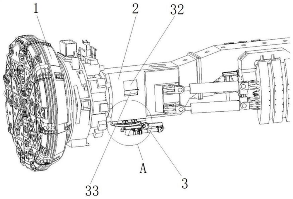
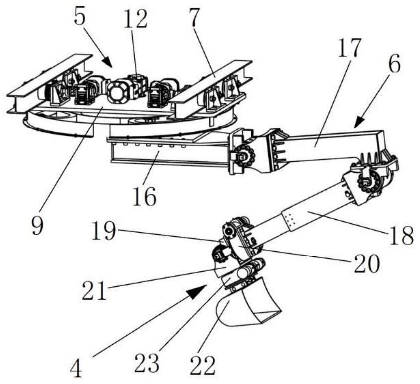
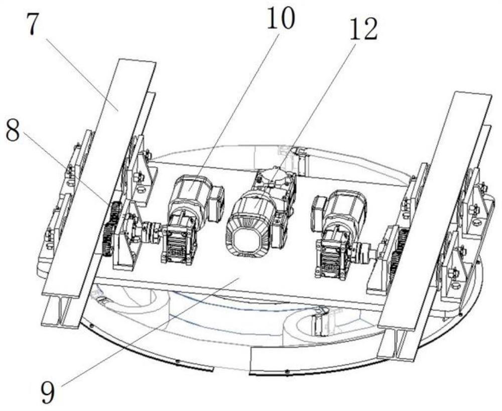
[0084] The partial structure of the boring machine provided by this embodiment is as follows: figure 1 As shown, it includes a cutter head 1 and a main beam 2 arranged on the rear side of the cutter head 1. The main beam 2 is provided with a slag for transporting the earth and rock excavated by the cutter head backward (defining the direction of the excavation of the roadheader as the front). For the soil conveyor, in order to clear and transport the accumulated earth and rocks at the bottom of the tunnel to the muck conveyor, the roadheader also includes a slag removal device 3 arranged on the main beam 2 . In this embodiment, the muck conveyor is a belt conveyor, and in other embodiments, the muck conveyor may also be a bucket conveyor. In a...

specific Embodiment 2

[0103] The specific embodiment 2 of the roadheader provided by the present invention differs from the embodiment 1 mainly in that in the embodiment 1, the slag cleaning bucket pours out the slag material at the slag discharge position. In this embodiment, a discharge door is provided at the bottom of the slag cleaning hopper, and a driving device for driving the opening and closing of the discharge door is provided. When the slag cleaning hopper reaches the discharge position, the control system controls the driving device to drive the discharge door to open , realize unloading.

specific Embodiment 3

[0104] The specific embodiment 3 of the roadheader provided by the present invention mainly differs from embodiment 1 in that in embodiment 1, the connection seat is a rotating seat that can rotate relative to the fixed part of the main beam, so that it can be cleared. The position adjustment of the slag hopper is more flexible and convenient. In this embodiment, on the premise that the slag cleaning hopper of the slag cleaning device can be accurately moved to the position of the slag material by moving along with the excavation, the connecting seat may not be a rotating seat, that is, it may be a fixed structure as a whole.

[0105] The specific embodiment 4 of the boring machine provided by the present invention differs from the embodiment 1 mainly in that in the embodiment 1, the movable arm is composed of two boom segments. In this embodiment, the movable arm is composed of three boom sections. Certainly, in other embodiments, the movable arm may have more than three sec...


PUM


Abstract

The invention belongs to the field of tunnel excavation equipment, and particularly relates to a tunneling machine slag removal device and a tunneling machine. The tunneling machine comprises a cutter head, a main beam connected to the cutter head, an equipment bridge located on the rear side of the main beam and a slag conveyor, and further comprises a slag removal device with a slag removal mechanical arm and a slag removal hopper; the slag removal mechanical arm comprises a connecting base connected with the main beam and / or the equipment bridge and a movable arm hinged to the connecting base, the movable arm comprises at least two arm sections, driving devices for driving the corresponding arm sections to be unfolded and folded are arranged between the arm sections and the connecting base and between the arm sections, and the slag removal hopper is connected to the last-stage arm section. The active slag removal hopper can be driven by a slag removal mechanical arm to actively take slag, the slag removal hopper is provided with a slag discharging position for feeding the taken slag into a slag conveyor on a main beam of the heading machine, and the slag removal hopper is provided with a discharging door and a discharging driving device. Or a material pouring driving device for driving the slag removal hopper to pour out the slag is arranged between the slag removal hopper and the slag removal mechanical arm, so that automatic slag removal is realized.

Description

technical field [0001] The invention belongs to the field of tunnel excavation equipment, and in particular relates to a slag cleaning device for a roadheader and a roadheader. Background technique [0002] At present, roadheaders have become an important equipment in tunnel construction projects, and are widely used in water conservancy tunnels, urban rails, municipal transportation and railway tunnels and other fields. As a typical tunnel boring machine, TBM (full-face hard rock tunnel boring machine) is often accompanied by rockburst, top collapse and block falling during the tunneling process, resulting in serious slag accumulation at the bottom of the tunnel. If the slag and stones are cleaned If it is not timely, it will lead to delays in the assembly of arches, inverted arch blocks, and track laying, which will restrict the construction progress and affect the quality of support. [0003] At present, there are two main ways to clean the slag at the bottom of the tunn...

Claims


Application Information

Patent Timeline
IPC IPC(8): E21D9/12E21D9/11
CPCE21D9/126E21D9/11
Inventor 卓兴建孙颜明原晓伟王一新李正道贾连辉姜礼杰张凯
Owner CHINA RAILWAY ENGINEERING EQUIPMENT GROUP CO LTD
Learn More