
Vibration isolator

a vibration isolation and elastomeric grommet technology, applied in the manufacture of springs/dampers, rubber-like material springs, vibration dampers, etc., can solve the problems of excessive and undesired maintenance, short lifespan of elastomeric grommets, and accidental loss of components, so as to reduce the natural frequency of vibration isolators and reduce the occurrence of replacement and repair. , the effect of good high frequency performan

Active Publication Date: 2018-05-24
ITT MFG ENTERPRISES LLC
View PDF1 Cites 4 Cited by
  • Summary
  • Abstract
  • Description
  • Claims
  • Application Information

AI Technical Summary

Benefits of technology

The patent describes a vibration isolator that has good performance at high frequencies. It has a resilient core that is bonded to the surfaces inside the isolator, which reduces its natural frequency. This makes it less sensitive to vibrations. The resilient core also lasts longer and is less likely to need replacement or repair.

Problems solved by technology

As a result, these components are subject to being accidentally lost during installation of the vibration isolator.
Furthermore, these elastomeric grommets typically have a short lifespan, as compared to the remainder of the isolator assembly, due to friction between the components under loads experienced during operation, requiring excessive and undesired maintenance as well as related costs.

Method used


Image

  • Vibration isolator
  • Vibration isolator
  • Vibration isolator

Examples


Embodiment Construction

[0036]The following description should be read with reference to the accompanying drawings, in which like elements in different drawings are identically numbered for the sake of clarity. The drawings, which are not necessarily to scale, are intended to depict salient features of the design in selected embodiments and are not intended to limit intended scope. The following description illustrates by way of example, not by way of limitation, the principles of the invention. This description will clearly enable one skilled in the art to make and use the invention, and describes several embodiments, adaptations, variations, alternatives and uses of the invention, including what is presently believed to be the best mode of carrying out the invention.

[0037]In addition, various terms are used throughout in order to provide a suitable frame of reference with regard to the accompanying drawings such as “bottom”, “upper”, “top”, “within”, “lateral”, “upon”, “front”, “back”, “inner”, “outer”, ...


PUM


Abstract

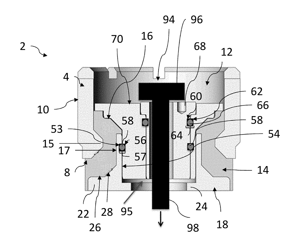
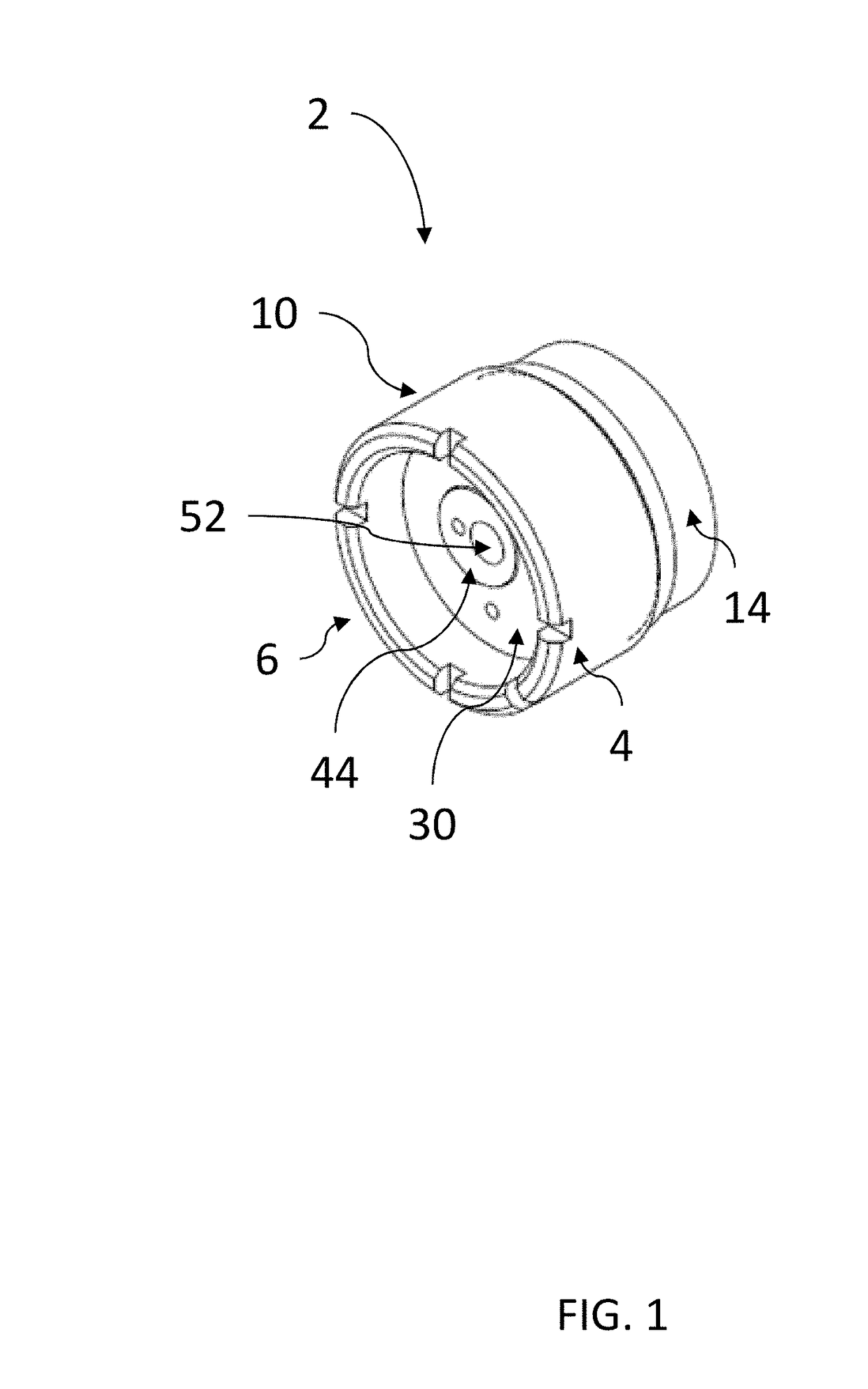
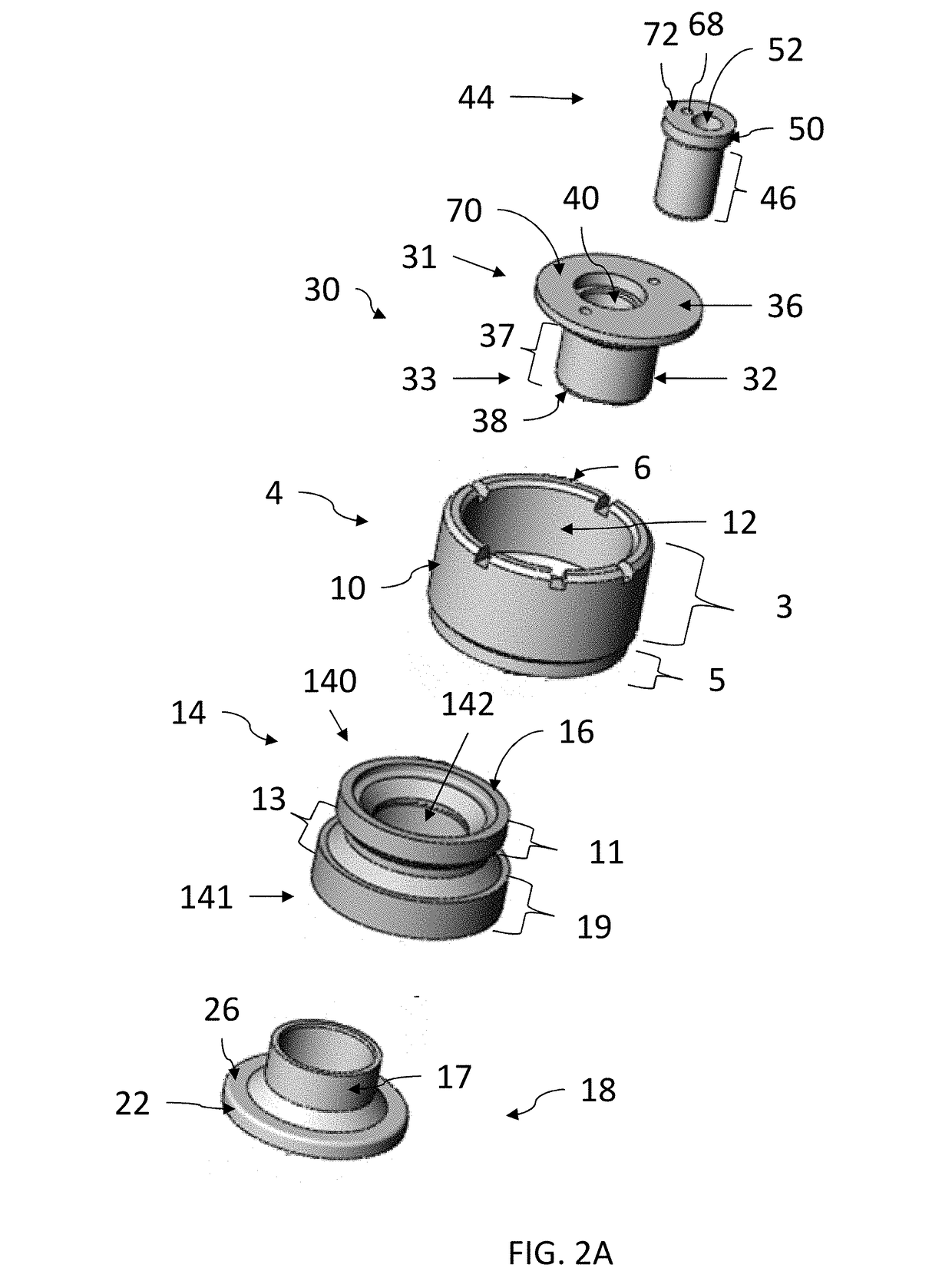
A vibration isolator includes a housing having a top surface, an opposing bottom surface, and a hollow interior and an open-ended sleeve having a hollow interior and an extending flange, the extending flange having a top surface and a bottom surface. A resilient core, having a hollow interior, is positioned between and fixedly coupled to the bottom surface of the housing and the top surface of the flange of the sleeve. The resilient core is disposed within a portion of the hollow interior of the open-ended sleeve. A first bushing is disposed within the interior of the sleeve. The first bushing has a flange including a bottom surface that overlays a top surface of the resilient core. A second bushing is disposed within the first bushing.

Description

CROSS REFERENCE TO RELATED APPLICATION[0001]This application claims priority upon U.S. Patent Application Ser. No. 62 / 425,734, filed Nov. 23, 2016, under relevant portions of 35 U.S.C. § 119 and 37 CFR § 1.53. The entire contents of this document is hereby incorporated by reference.TECHNICAL FIELD[0002]This application generally relates to the field of vibratory isolation and damping assemblies and more specifically to a vibration isolator that isolates a cabinet or other fixture or structure from vibrational loads.BACKGROUND[0003]Vibration isolators and damping assemblies are commonly used in a number of disparate fields in order to isolate various structures from vibration loads. For example, high-end business aircraft typically have seats, tables, credenzas, stereo and TV cabinets, glassware, etc., collectively known as “monuments”, installed therein. These monuments are coupled, such as through a fixed bolted connection, to a seat track or other structural rail formed in the flo...

Claims


Application Information

Patent Timeline
Patent Type & Authority Applications(United States)
IPC IPC(8): F16F1/38
CPCF16F1/38F16F1/3842F16F2236/123F16F2226/04F16F1/3863
Inventor SENNEFF, JAMESDOWNING, MARSHALL
Owner ITT MFG ENTERPRISES LLC
Learn More