Misuse detection method, misuse detection electronic control unit, and misuse detection system

a technology of misuse detection and misuse, applied in the field of misuse detection electronic control unit, misuse detection system, misuse detection method, etc., can solve problems such as the access of attackers to busses

Active Publication Date: 2018-05-24
PANASONIC INTELLECTUAL PROPERTY CORP OF AMERICA
View PDF5 Cites 17 Cited by
  • Summary
  • Abstract
  • Description
  • Claims
  • Application Information

AI Technical Summary

Benefits of technology

[0008]According to the present disclosure, a possibility of erroneously detecting an authorized frame as an unauthorized frame is reduced even if an unauthorized node is connected to buses of the CAN and an unauthorized frame is transmitted, and the transmission of the unauthorized frame can be appropriately detected.

Problems solved by technology

In a vehicle network system according to the CAN, there is a threat that an attacker might access busses and transmit an unauthorized frame to improperly control ECUs, and security measures are being examined.

Method used


Image

  • Misuse detection method, misuse detection electronic control unit, and misuse detection system
  • Misuse detection method, misuse detection electronic control unit, and misuse detection system
  • Misuse detection method, misuse detection electronic control unit, and misuse detection system

Examples


first embodiment

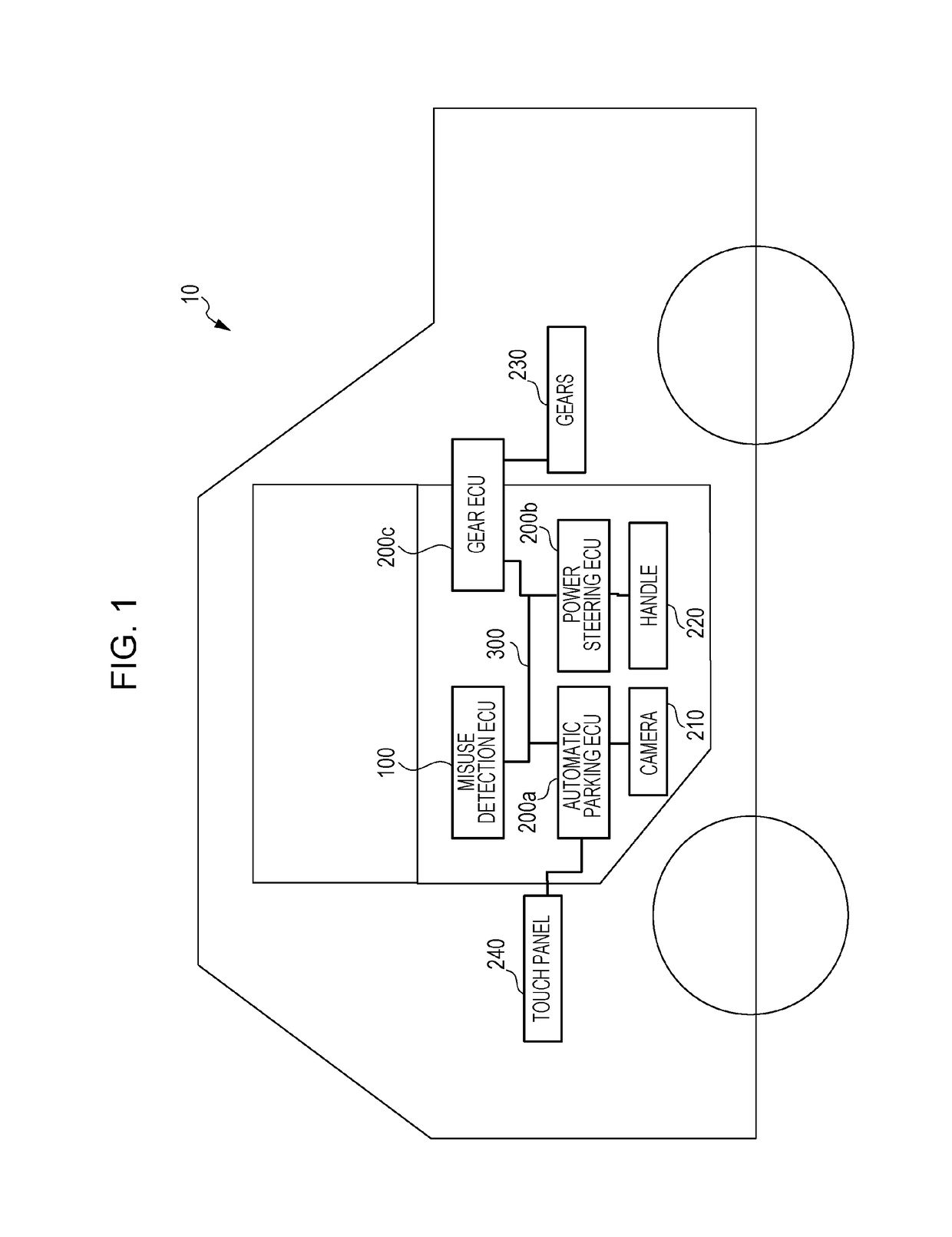
[0047]A misuse detection method used in a vehicle network system 10 with which a plurality of ECUs communicate through buses will be described hereinafter with reference to the drawings as an embodiment of the present disclosure.

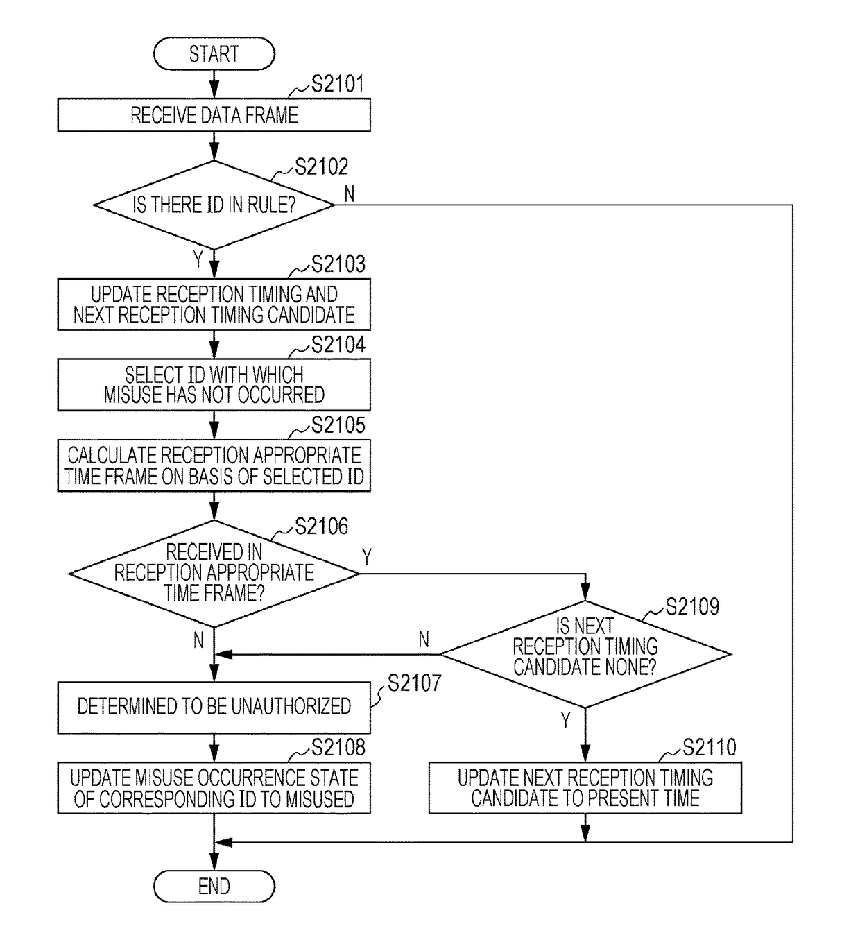
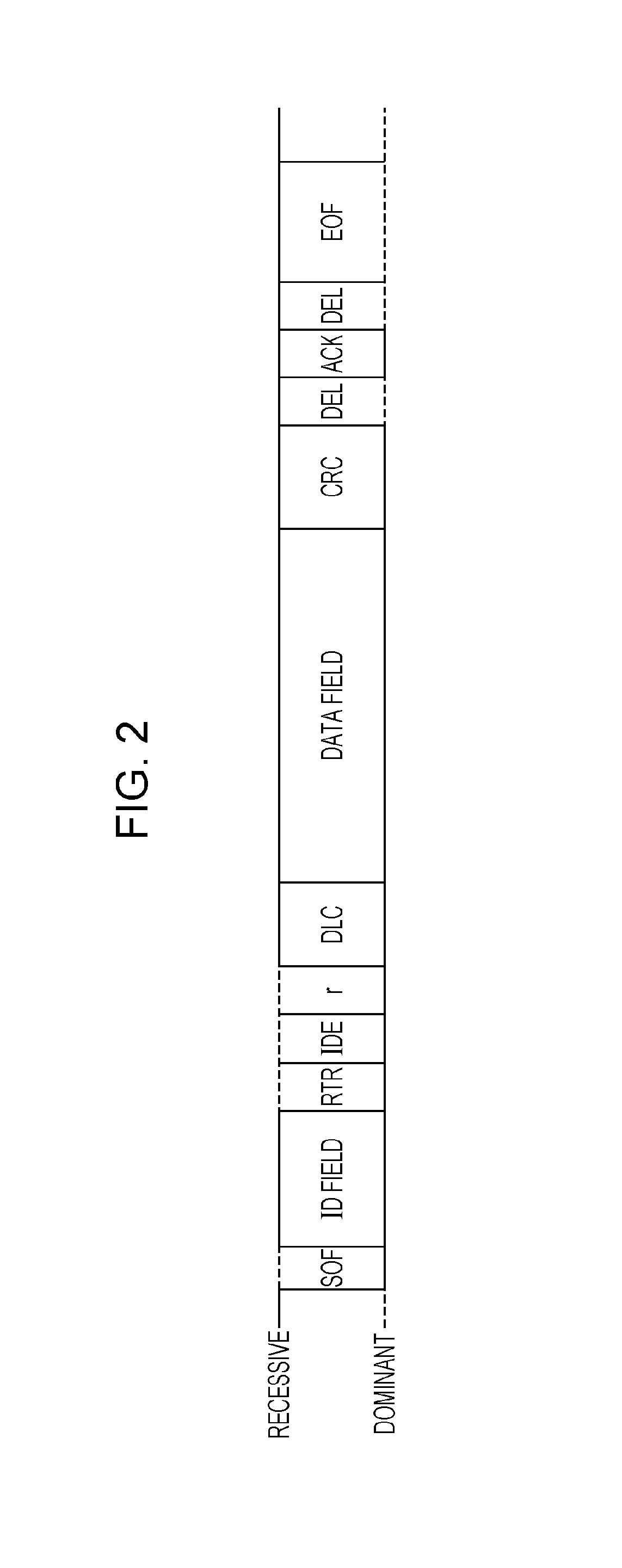
[0048]The misuse detection method is a method for detecting an unauthorized frame transmitted after an unauthorized node is connected to buses of a CAN and mainly implemented by a misuse detection ECU connected to the buses. A misuse detection ECU 100 in the vehicle network system 10 detects an unauthorized data frame on the basis of a reception interval between data frames (messages) having two different identifiers (message IDs). As a result, if an unauthorized data frame is transmitted, a possibility of erroneously detecting an authorized data frame having the same identifier (message ID) as the unauthorized data frame as an unauthorized data frame is reduced.

1.1 Overall Configuration of Vehicle Network System 10

[0049]FIG. 1 is a diagram illustrating the ...

second embodiment

[0116]A vehicle network system 11 obtained by partially modifying the vehicle network system 10 described in the first embodiment will be described hereinafter.

[0117]The vehicle network system 11 according to the present embodiment uses a misuse detection method in which a data frame that serves as a reference for a reception interval for a data frame subjected to misuse detection is switched. First, a determination whether a data frame is unauthorized is made on the basis of a reception interval between data frames having the same ID, and if it is determined that the data frame is unauthorized, another determination whether the data frame is unauthorized is made on the basis of a reception interval based on a data frame having another ID with which misuse has not been detected.

2.1 Overall Configuration of Vehicle Network System 11

[0118]FIG. 11 is a diagram illustrating the overall configuration of the vehicle network system 11 according to the present embodiment.

[0119]As illustrate...


PUM


Abstract

A misuse detection electronic control unit in a vehicle network system including a plurality of electronic control units that communicate with one another through buses in accordance with a CAN protocol includes a transceiver unit that performs a reception step of receiving a target data frame and a reference data frame transmitted through the buses, wherein the target data frame is a data frame having a first identifier and wherein the reference data frame is a data frame having a second identifier different from the first identifier and a misuse detection process unit that performs a detection step of performing, as misuse detection for the target data frame, evaluation in accordance with a reception timing of the reference data frame and a reception timing of the target data frame on the basis of a certain rule specifying a reception interval between the reference data frame and the target data frame.

Description

BACKGROUND1. Technical Field[0001]The present disclosure relates to a technique for detecting transmission of an unauthorized frame in a vehicle network in which electronic control units communicate with one another.2. Description of the Related Art[0002]During these years, a large number of devices called “electronic control units (ECUs)” are provided in a system inside an automobile. A network connecting these ECUs with one another is called a “vehicle network”. A lot of standards exist for vehicle networks. A standard called a “controller area network (CAN)” specified in International Organization for Standardization (ISO) 11898-1 exists for one of principal vehicle networks.[0003]In the CAN, a communication path is configured by two buses, and ECUs connected to the buses are called “nodes”. The nodes connected to the buses communicate messages called “frames”. A transmission node, which transmits a frame, applies voltage to the two buses to generate a potential difference betwee...

Claims


Application Information

Patent Timeline
Patent Type & Authority Applications(United States)
IPC IPC(8): G06F21/44B60R16/023G06F13/40
CPCG06F21/44B60R16/0231G06F13/4027H04L63/1466H04L12/40H04L12/40169H04L63/1416B60R16/023B60R16/02B60W50/04G06F21/85G06F21/554
Inventor KISHIKAWA, TAKESHIUJIIE, YOSHIHIROMAEDA, MANABUMATSUSHIMA, HIDEKIAMANO, HIROSHINAKANO, TOSHIHISA
Owner PANASONIC INTELLECTUAL PROPERTY CORP OF AMERICA
Why Eureka
Try Eureka